Intro to Digital Fabrication
TUTOR: Djordje Stanojevic
The Digital Fabrication was a studio to explore different techniques and materials to model a physical Design. Each of them are used depending on the type of geometry and the concept. 3 Testing have been made:
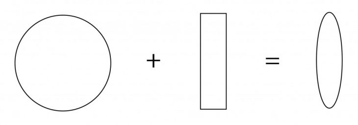
Ellipsoid Pattern
DATA
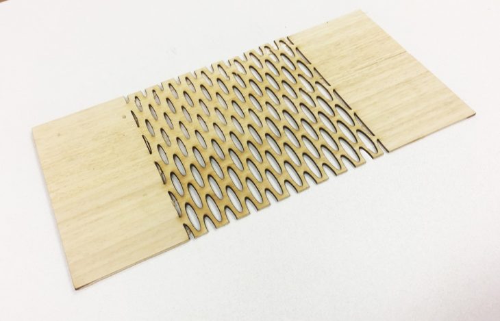
Material:Wood / Technique: Laser Cut
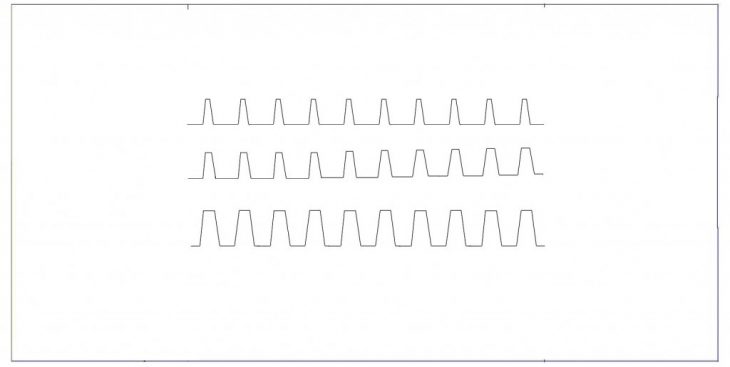
CONCEPT I am working on an ellipsoid pattern. Starts with small openings from the left side above and become big at the right side. The best one to choose is the second one because the curving linear is acceptable and the distance between the voids doesn’t go below 1.5mm ( minimum distance between the voids).
Concept
Option 1 (minimum distance)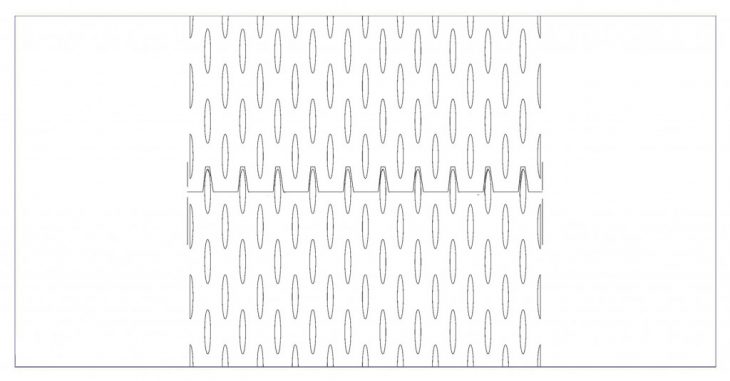
Option 2 (Gradient with attraction point)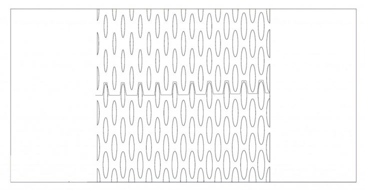
Option 3 (Highest Distance)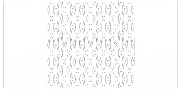
3 Silhouettes (3 Linear dimensions separated)
Model
First I defined the shape of the void as ellipsoids on the Grasshopper script. Then I defined the minimum, normal and maximum separation distance between them by using the slider command. I bake them and compare them on 3 graphs where I can compare the different options.”
In conclusion, the second option was chosen (the normal separation) because it has the acceptable distance between the voids.
Landscape path Design
DATA
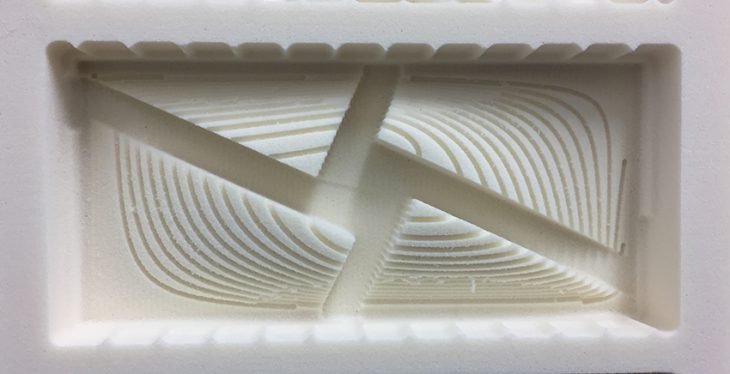
Material: Foam / Technique: CNC Milling
CONCEPT
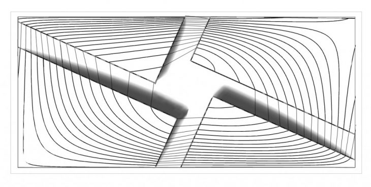
The concept is the create a landscape design where geometry and topography join together. I obtain a landscape architecture inspired by the Blavand Bunker Museum designed by BIG ( Bjarke Ingels):
Top view plan
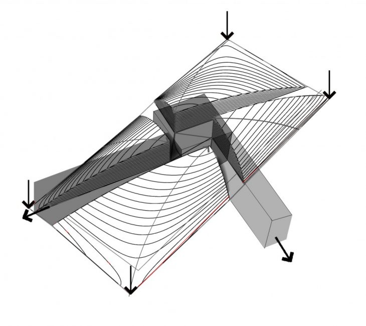
 Diagram
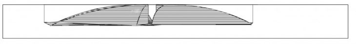
Face elevation
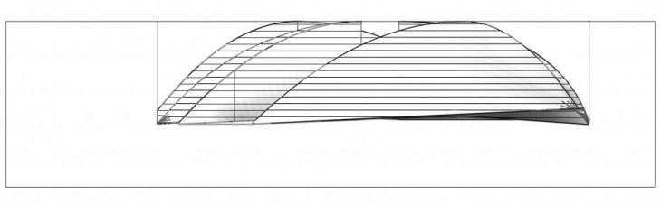
Horizontal Elevation
METHODS
First I defined the 2 directions’for paths by using the patch command where I can obtain the lowest and highest levels. Then I subtract by using the Split command between the new topography volume and boxes (as shown on the schematic 3D process on the pdf). I also subtract the middle of the shape by creating a plaza where the 2 Paths join.
In conclusion, I Obtain a designed landscape using the CNC milling where we can easily understand the concept by using the materials need.
Dynamic Serpentines
DATA
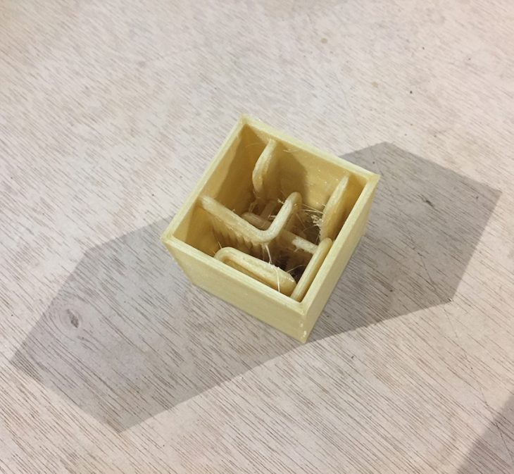
Material: PVA & Resin Casting Technique: 3D’printing
CONCEPT
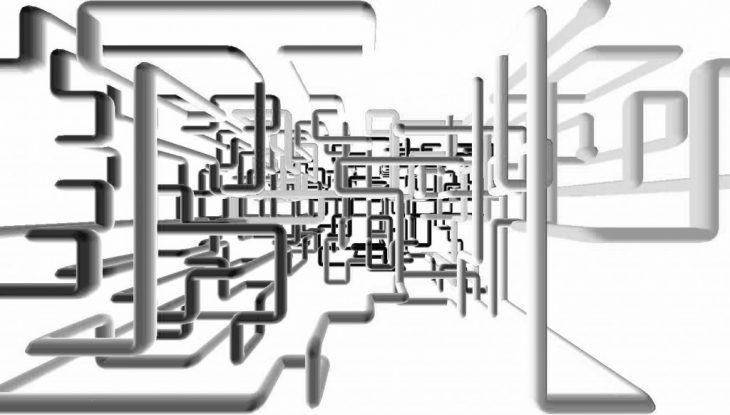
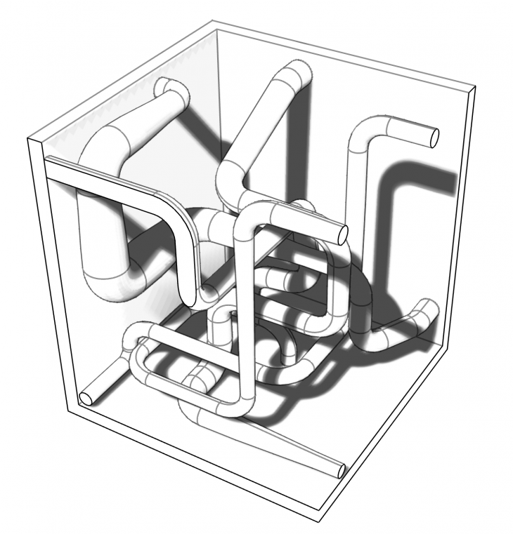
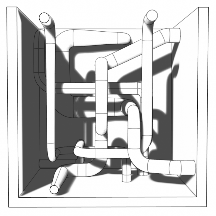
The concept is to create a contrast between the inside and outside of the box. Different directions of serpentine moving in all the directions without hitting each other.
Windows screensaver
Diagram

3D View
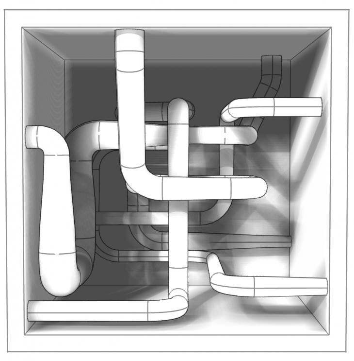
Traversal View
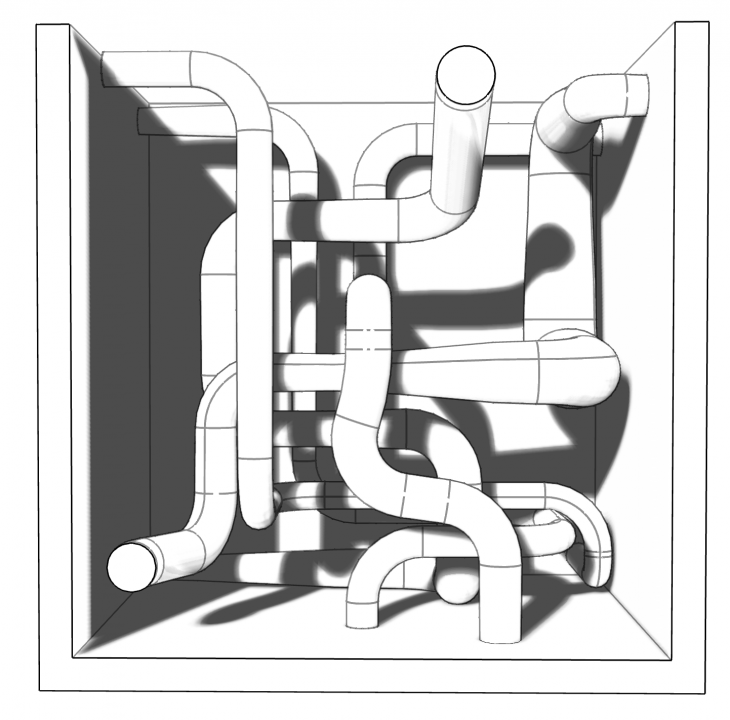
Longitudinal View
3D Render Model
l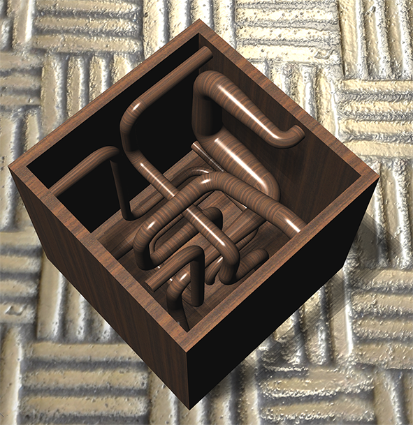
Model
METHODS
First I defined 5 directions where my paths are going to be defined. Each time they move, a 90 degree angle is used but with a smoothly way. They start from the top to the lower level of the box. They are connected to the 6 planes of the cube so we can obtain dynamic directions. Then I created Tubes Flat caps where their diameter varies from the beginning to the end of the path and we can obtain different types between each other.
In conclusion, when we observe inside the calm box,we obtain a dynamic interior that expands and get the attention of the audience.
I want to thanks our tutorials Djordje and Kunaljit who guided and learned us to improve our knowledge of executing real physical design with different types of machines and materials.
Frederick Ajjoub, Student in Master of City and technology (Mact)