ARK – FOOD SCIENCE LAB
MASS TIMBER FOR LARGE FACILITIES
BIRMINGHAM I UK
![]()
SITE ANALYSIS
The site is located at Smithfield, Birmingham, UK. The plot is part of a bigger master plan of the area of Smithfield Historical Markets. New uses are going to be introduced by creating 4 city quarters, such as the cultural quarter, the city market exchange, the creative tech gateway, and the new residential development. A new pedestrian network is designed for the whole area while the plot is located in the middle of the new uses acting as an urban capacitor. The plot has a slope of 4m at its lower part and connects the Smithfield gardens with the St. Martin’s Church through a green boulevard. To this end, the main idea of the new usage is to create a Food Science Lab in order to welcome people to learn about starting point of a seed, the food culture through different cuisines (such Roman, Ancient Greek, Local, and so on) and participate in workshops available for adults and kids as well. The laboratories may act as the scientific research department of the markets developed in the surrounding area.

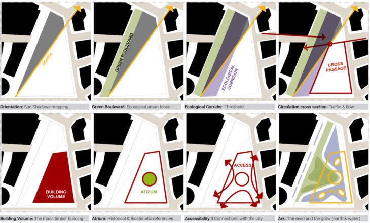
INTEGRATION ANALYSIS DIAGRAMS
The starting point of the architectural design is the North-South axis orientation which according to the sun study outline the areas that are mostly under the shadow. The next step is to create the green boulevard at the west outline of the plot and then create an ecological corridor as a threshold between the civic and the building. The cross-access passage creates a new node at the point of intersection of all lines going through it. In the end, the massing of the building shown in red color is created to the remaining empty space. The mass is trimmed at the center to create an atrium of a similar diameter to the music center building on the west side. The city-scale is connected with the mass timber building through 3 curved pathways which they in turn correspond to the 3 main platforms of the entrances. The undulated landscape of the urban forest is combined with water surfaces to enhance the microclimate of the area around the mass timber building.
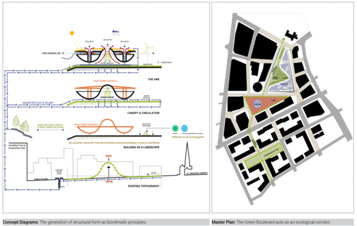
CONCEPT
The main architectural idea is related to the cultivation of the seed as a symbolic reference to the food and nutrition dynamics. The Food Science Lab, named the ARK has metaphorical and inspirational meaning as it is created through the unfolding of the earth to form the first shape of the building. The backfilling of the area to a horizontal platform according to the slope is et to 4m. at the lower corner. There are already some strategies, such as smart apps that can be found in cities of North America and extend their theory in Europe, where the contractors or even architects can find some re-used components which can include in their projects. In our case materials extracted from the demolition of existing buildings are used as a backfilling. The mass timber roof canopy with the LVL circular pillars is attached to the building and creates the upper floor level in between. The roof structure with the glass vaults enhances the natural lighting airing and ventilation of the building, while water is recycled and reused for interior usage and irrigation. The building is integrated into the whole master plan of public plazas and green parks with the aim to minimize its ecological footprint while maximizing its positive impact on the environment.
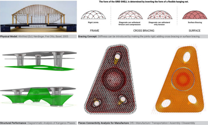
STRUCTURAL EFFICIENCY DIAGRAMS
When designing long-span timber structures we have to consider the following:
- Loading (snow, wind, thermal)
- Robustness (accidental loading)
- Deflection (ponding)
- Fabrication limitation
- Transport to site
- Installation (construction sequence, temporary works)
- Connections – critical in the design
- Fire requirements
- Lateral stability
- Roof drainage
- Efficient use of materials (avoiding an excessive amount of timber material)
In order to simulate the structural performance of the structure, we have to create a continuous surface on the ground level and then relax it to the shape of the form to naturally distribute the forces. This process is achieved by using a Kangaroo coding at Grasshopper. The pieces connectivity analysis shows that almost 85% of the pieces can be assembled into larger groups with mostly single curvature with radii and the other 15% should be assembled one by one with double curvature components. Then we have to specify the bracing concept so as to proceed to the most suitable option for the grid mesh pattern.
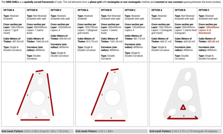
GRID MESH PATTERN DIMENSIONING TYPOLOGIES
In order to proceed with the best alternative of the grid shell structure, we have to combine different structural grids and layering of the elements so as to achieve less self-weight, more strength, and less amount of timber used. In our analysis, we have created 3 scenarios with grid mesh patterns of the grid shell where we apply 3 different construction logics to all of them (strained grid shell, not-strained grid shell with radii, strained grid shell with radii). So we finally created 9 different options and simulate them to generate the structural dynamics. We concluded that a triangular 3 directional grid mesh pattern of 2.00×2.70×2.70m with 6 layers of 100mmx400mm LVL Douglas Fir Timber elements has the best performance and the less cubic meters of timber used. This is also related to the brain concept of diagonals that can withstand tension and compression.
Regarding the efficiency of the grid mesh pattern even though visually it might look like complicated and lots of timber in the ribs or the frames, is actually a low number of cubic meters of timber when compared to just the roof slabs. The roof slabs have a high volume of timber. So this is often why having a smaller span and more timber in beams and columns can significantly reduce the timber volume in the whole building because most of the volume tends to be in the floor slabs or the roof slabs. In this case, we can consider the thickness of the floor and roof to be thinner probably almost 35% for a span of 2m or less for CLT decks.
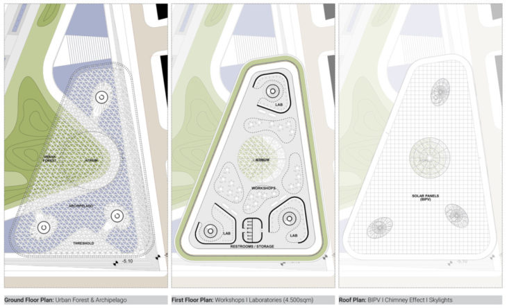
MAIN PLANS
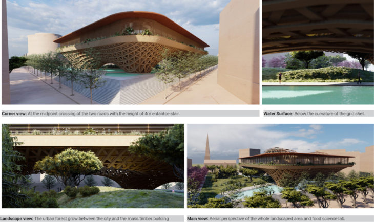
The building is hovering above the ground and the water surface as a topological state-of-the-art technological artifact. The entrance to the building is accessed on the ground floor by three openings on the grid shell and is connected with the LVL circular stair and lift cores. These cores are also used for emergency escape in case of fire. The first-floor level accommodates the Workshop area and Laboratories, and this means that the architecture program requires a flexible open space. So, If we think of the roof structure as a shell we don’t need columns inside. In this case, we are using a grid shell roof connected with LVL supports arraying circularly around the LVL cores and holding the grid shell of the roof. The main idea is to have a flexible open space to be separated with movable curtains for workshops as well as having 3 main cores around the cores for the Laboratories and one auxiliary core for the restrooms and storage areas. The roof is covered with copper and glazing skylights while the whole roof is covered with BIPV panels.
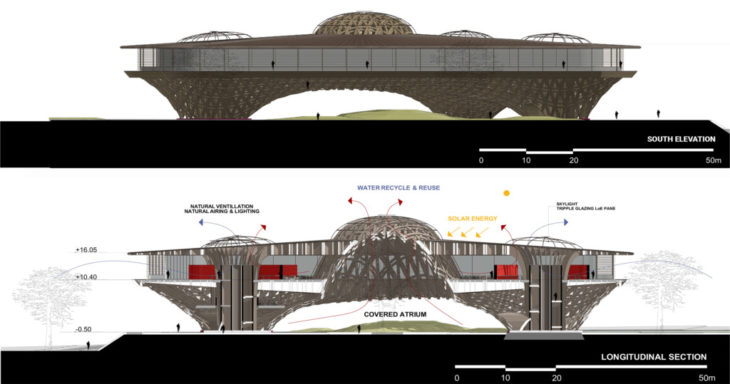
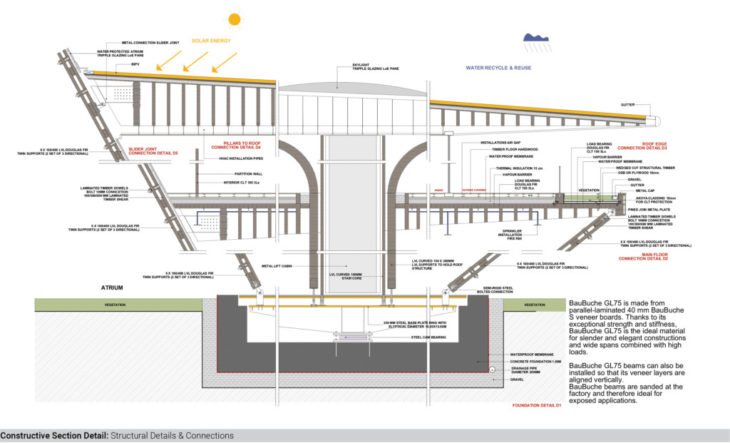
MAIN ELEVATION & BIOCLIMATIC SECTION
Plywood is not the best option for façade. Traditionally timber is painted. So in order not to have painted timber and at other same time resist weathering, we have to do two things. One is to cover the façade with an overhang to protect it from sunlight and grey pattern weathering issues, and the second is to use high-quality wood species, such as Akoya Pine for cladding. Accoya starts life as a fast-growing pine tree (Pinus radiata) grown in managed forests. The pine tree is harvested once it reaches maturity at around the 30-year mark. It’s at this point its journey isn’t the same as other timber. We introduce the raw timber to a modification process as a plank or beam, the so-called acetylation process using acetic acid. This process creates extremely dimensionally stable and durable wood. Accoya wood is highly rot-resistant and very stable across varying climates. Containing no toxic substances as the process simply increases the levels of already present elements within the molecular structure of the wood. Every piece of Accoya has been modified through to its core, providing the same performance and protection no matter how the wood is cut, planed, drilled, shaped, or more. This makes Accoya ideal for many applications including window frames, doors, façades, cladding, and decking, all without the use of preservatives. Accoya wood is Class 1 durable and surpasses even the most durable old-growth tropical hardwoods such as teak. The production of Accoya is based on the process of wood acetylation. Scientists have proven that this modification process is an incredibly effective method to improve the technical properties of wood. Wood acetylation works by changing the cell structure of the wood whereby the cell walls are “blocked” for moisture absorption. This modification reduces the wood’s ability to absorb water in the cell walls by about 80%, greatly improving dimensional stability, resulting in Accoya requiring less maintenance. The change in cell walls means that insects and fungi do not recognize Accoya wood as a food source and therefore do not attack. Perfect for those parts of the world with termites or other wood-eating critters. Purpose-grown Radiata Pine forest – New Zealand.
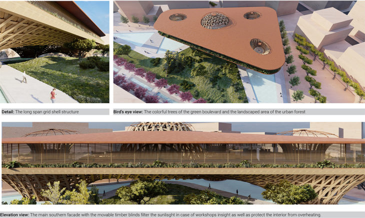
In addition, the perimetrical glazed surface of the first floor is protected from sunlight by using horizontal movable timber louvers that on the one hand filter the amount of light required to enter and on the other hand reduce the solar radiation as well as the energy requirements for heating and cooling of the interior spaces. The skylights of the 3 main cores and the atrium offer plenty of natural lighting to the interior spaces while they are also used as solar chimneys to remove heat air from the building by enhancing natural airing and cross ventilation of spaces as well. The water surface on the ground floor enhances the microclimate by reducing the average air bulb temperature through evaporation. Finally, the grid shell structure is not covered by surface cladding helping the air to move around the building so in this case, the building doesn’t act as an air mass barrier.
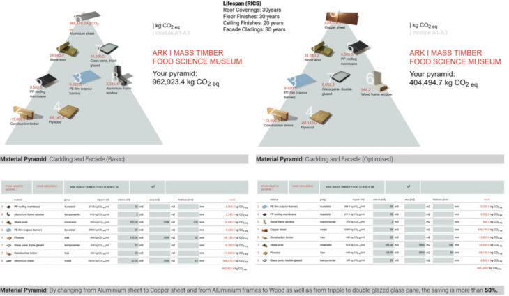
MATERIAL SELECTION & LIFESPAN
The construction sector is responsible for over 35% of the EU’s total waste generation and accounts for about 50% of all extracted resources and an estimated at 5-12% of total GHG emissions. Waste generation is produced not only during construction but also at the end of the life of a building where a very little part of the components is going to be reused. The existing building stock is a huge material bank that is not designed for circularity. New building stock must be designed for circularity and at the same time be able to re-use materials “extracted” from the demolition of existing buildings. So all the interfaces and all the connections, and even the choices of the materials to basic strategies to think about building components and building assemblies to be possible to think these buildings as minds, to extract parts of it and re-use them ideally completely in other buildings.
In our case, by changing from Aluminium sheet to Copper sheet for the roof and from Aluminium frames to Wood as well as from triple to double glazed glass pane, the saving is more than 50%.
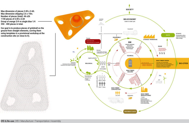
CIRCULAR BIO-ECONOMY – BIM – MASS TIMBER BUILDINGS
Circular economy is depicted in green color, outlining the outer shell of the two cycles; the biological and the technical. The biological cycle is related to the biosphere, while the technical is related to the manmade environment according to the SDG’s. People play the role of agents between the two cycles and for this reason are placed on the connection joint.
BIM is depicted in red color and contributes to a material database of mass timber design and construction and has to be pared with blockchain (distributed data technologies). A database that can interface with BIM and probably this database has information about the forest in the near future. BIM in this case is a material passport that contains all the information of the material and is connected with the product data, use, disassemble and reuse.
Mass Timber processes are depicted with orange color while the building itself is placed at the main core of the technical cycle. Mass timber design and construction lead to the circular bio-economy through the BIM processes while connecting the technical and biological cycle throughout a project’s lifetime.
INSTALLATION SEQUENCE DIAGRAM & LIFESPAN INFLUENCE ON LCA ANALYSIS FOR TIMBER
An important thing of complex geometries is firstly to understand how to optimize the efficient shape of the structure and secondly how the elements that form the structure are put and joined together with the rest of the components of the building.
In this direction we analyze two scenarios to follow:
A. If scenario one is to create small pieces joined together on-site, it is required to produce minimal repeated components which will be easier to re-use due to standard sizes which are plentiful. The kit of parts comprises dry, mechanically connected repeated components with greatly improved end-of-life prospects. Note that components may require some post-disassembly processing before they can be used in a new building. The kit of parts is easy to be transported to the site although it requires a large area to assemble the whole structure on-site and protect the components from weather conditions during construction time. By installing all parts one by one on-site we have to deal with the problem of too many connections while when the assembly of the whole structure is completed on the ground it is not an easy process to lift the whole structure to the roof level.
B. If scenario two is to fabricate bigger pieces in a controlled environment of a manufacturing facility we can achieve faster production with less cost. The advantages of creating larger pieces out of smaller ones on-shop include the controlled weather conditions and temperature, the use of well-trained factory staff, and the utilization of all available equipment and machinery to implement the best tolerances and connections. The only aspect we should bear in mind with this scenario is to keep the maximum dimensions of the assembled pieces no larger than the truck dimensions to be transported on-site. The larger pieces are joined together directly to the roof level by a crane and a few workers. The construction time is even faster than the first scenario and the noise disturbance and dust particles dissemination to the neighboring areas during the construction are lower as well.
A combination of scenarios A and B will be to produce pieces and assemble bigger parts on the ground from straight elements, curving them using templates in a “provisional” shop factory at the construction site (or very close) and from there install them. This was the solution used for big roofs such as in Hannover Expo.
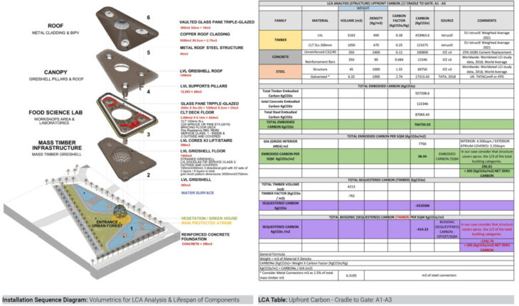
The carbon sequestered in a tree has already been absorbed from the atmosphere. The benefit of sustainability to being responsible is to protect wood so as not to release carbon back into the atmosphere. So, this is one of the reasons to build with wood and not leave trees unprotected from fire and decay. This has a duration of 60-70 years. The longer the lifespan of the structure the less risk we take. DfD is related to the lifespan of the components so if it lasts long enough to reach net zero. The net-zero target of 300kgCO2e/m2 is an aspirational target. So what else we can do to offset the embodied carbon. Plant more trees? How many? The importance is balance. For the purpose of our exercise, we consider only structural elements. So we have to think about the floor, roof, stairs, foundations, and connectors. If you are using timber to timber connections is ok but if we are using metal connectors we have to approximately specify 1.5% of the total timber volume for steel volume for these connections. (even though CLT is a bit more and LVL a bit less but is almost somewhere near this number).
When we are designing, we get more accurate information regarding how much energy is actually being used and put it in the building upfront. While in use is an estimate because we roughly know how the building is going to be used during its lifespan of 60years. And the same at the end of life-based on the knowledge we have today. We really need to focus on upfront carbon. And to see the implications that may cause at the end of its life. Categories A1 to A3 are the most accurate information the industry can offer today, so it is important to use generic data at the early stage to see if this is an achievable target.
One of the principles of reducing carbon is
- massing (creating mass by surface)
- height. (the more height doesn’t make the building more sustainable – you use a lot of material in order to support these stories).
To understand how this fits the net-zero picture, 20 years ago net zero carbon is balancing the energy to operate the building (KWh/m2 per year) with the amount of renewable energy required for the building (KWh/m2 per year) either with BIPV or wind turbines. Passive design minimized energy demand as well as uses energy from renewable sources. Now industries focus on how to balance the embodied carbon within the building either through offsetting – the scheme of being able to plant trees or by sequestering carbon within the building. Material choices minimize embodied carbon and sequestered carbon as off-setting.
Regarding the material pyramid, we see that the material at the bottom has a minus number as the embodied carbon figure. So they take the embodied carbon and the sequestered carbon and they mushed them into one number. So it will be the positive cost of making the product minus the whole saving stored within the timber. This is not the best way to do this because the cost of making the product is now, so it is an immediate saving, whereas the sequestered carbon is considered at the end of life. So it is really important not to put them tighter but better quote the two side by side, because what we shouldn’t be doing is throwing timber at a problem. Not just because it has this carbon storage ability it should be that we are irresponsible in how we specify other things such as façades and so on. So we have to focus on making the building fully sustainable.
Another thing to be careful of is the lifespan of our material. Some products have a small lifespan and you have to reuse them again and again. But particularly when we are talking about sequestration in mass timber, what we have to be aware of is that those trees are already grown and have already absorbed that carbon, so from day one when we are using them in our building is arguable that there is no positive benefit. The timber has already stored the carbon – as we just cut it down and put it in the building. So, the benefit is that as long as it comes from a sustainable forest those trees are allowed to regrow. A reasonable guess for softwood trees’ time to grow is about 60 years and this means that is balanced with the minimum 60 years lifespan of a timber building. So it is only by 60 years of our building to be reused to have the full sequestration benefit of that building. So that is why it is really important to separate that number out. Is it good to plant trees but it takes 60 years for that carbon to be absorbed.
VISUALISATIONS

DESIGN FOR DISASSEMBLY & REUSE
DfD is related to the component’s lifespan so if components have the ability to last long enough it is more possible to achieve net-zero KgCO2e/m2. Towards this direction, we understand that there are different levels of demountability, and what we should do is to translate our concept to a full disassembly or reassembly potential of the structure to a different location as far as the food science lab is concerned or to partially re-use the kit of parts of the project’s components such as glazing, timber panels, CLT decks, grid shell layers, and metal connectors.
In this case, we have created a full timber system that focuses on:
1. Dry products and mechanical fixings in lieu of adhesives, make it easy to separate different materials and elements without damage to components. Try to avoid glues or pour different materials together in a way they can’t be easily disassembled.
2. Modest and light component sizes. Relatively small light components facilitate demounting, also reducing the likelihood of damage and easing transportation for further processing or to a new site. From a logistical point of view, it is easier to transport smaller parts.
3. Access to connections. Connections made at a low level from the building interior allow for easy and safe installation and straightforward access for demounting. The prioritization process has to be thought out as it is important which element comes first, or second in order then to follow the same inversed logic to disassemble.
A really important aspect of demountability, a concept started almost 70 years ago, is to design interfaces to withstand more than one use. This means that the design of the connection between the components should have a tolerance not to damage components in order for the components to be easily disassembled and re-used. There are different families of connections we are always dealing with. We have to think about the impacts of solving a problem or defining or optimizing an interface that is brought to the entire system. We can connect materials in a low potential (glued) for disassembly ways or with high potential disassembly ways (bolts, friction, interlocking). In our case, we use bolts for the components to be easily disassembled, transported, and reassembled. Components identification and data. Components must be easily identifiable with quantitative and qualitative data available for future uses (eg. Through digital twin) as well as clear documentation of the method of deconstruction. BIM model – digital insight of the building. Building as a material catalog in this huge dataset – to understand which material is used and where and the quality of each component.
The type of glulam we are using internally is not the same as the timber we use externally, which requires a high durability class of timber. Tropical Hardwoods are not the most sustainable option but the most durable. Then spruce is cheap and fast-growing less durably softwood mostly used internally species. A typical service class 2 (outside and covered) is suitable to be used externally and timber selection will be Douglas fir. Service class 3 is generally what a softwood timber is treated to be used in external use and not in contact with the ground. Timber to timber connections would require a larger amount of timber. So to have thin elements is a bit difficult as timber-to-timber connections rely on friction. A bolted connection allows thin timber members as we basically have something squeezing that timber against it with a bolt together with Baubuche hardwood timber dowels, so it doesn’t matter how thick the timber is. When you start to become thicker you have to think screws. Can’t be so thin as the screw will reach the other side. So the elements should be thicker and as timber becomes thicker, timber-to-timber connections also become possible.
Our building is designed to R60. REI60 for load-bearing performance and fire suppression. Sprinklers slow down fire for a little bit of time as well as the exterior covered grid shell has hidden metal bolted connections.
There is a section of the EU code on how to measure to include external landscaping and it would be a nice story if part of the offsetting strategy will be to plant trees within the site because the climate will have more allowance to control how trees could be used in the future. Normally when we do offsetting or planting trees there is a sustainable forest that can guarantee the growth of trees and other processes. In any case equal to timber for buildings we must quote separately embodied carbon and sequestered carbon as regards timber for planting trees as well. Instead of using plywood for the roof covering, we can use a breathable cementitious board, then provide the building to be more breathable so we are less likely to get some moisture issues and have weatherproofed layers and this could probably be the external finish potentially. It is recommended to have a durable product behind a water membrane so as not to be affected by water. A porous water membrane is like if we touch a tent in rainy weather, and our hand gets wet. Beams and columns should be durable Douglas Fir treated glulam covered from the roof. We include also a weathering louver system in front of the opening of the HVAC roof to the ceiling to protect timber and HVAC systems from water as well. For the green roof of the first floor, we use Delta Geotextile as well as we are opening a few little holes to CLT, so in case the waterproof membrane fails, to protect CLT from bending or deformation.
Many thanks to Prof. Felipe Riola for the discussion and comments on grid shell structures.
—
Ark is a project of IaaC, Institute for Advanced Architecture of Catalonia developed at Master in Mass Timber Design in 2021/2022 by Student: Alexandros Kitriniaris. Faculty: Waugh Tristleton Architects. Course: Project 3