JOINERY RESEARCH / BAR + JOINT
We started our research delving into node connections. We found it very interesting how nodes could have the possibility to tie a series of simple linear elements while at the same time creating a complex structure due to its core geometry arrangement.
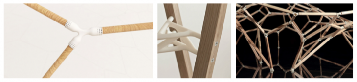
JOINERY RESEARCH / GEOMETRY
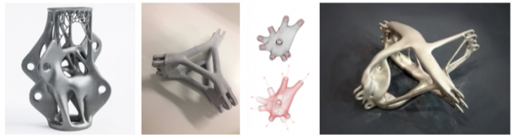
We investigated additive manufacturing techniques for nodes as we initially intend- ed to 3D print our set of pieces. We found a wide variety of examples which later on helped us make informed decisions even after we had scrapped the whole 3D print- ing process.
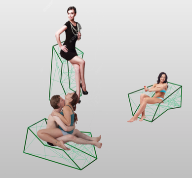
CONCEPT + CONFIGURATION
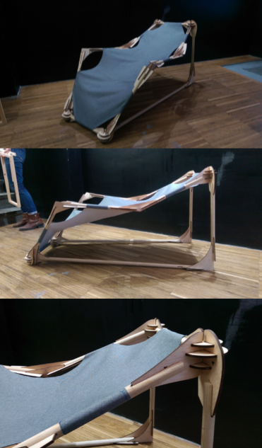
After having absorbed all the research, we moved on to generating the idea for our creation. Our concept was to design a chair which could be used in three different positions, made possible by the node optimization after the analysis of the geometry.
During the two-day workshop we had to limit ourselves to one position as we had a very short time to analyze and optimize for all of them.
WORKFLOW
1 Desired sitting scenario design – two people option.
2 Global analysis of system behavior when subjected to load
3 Joint analysis and refinement based on readings from analysis
4 Prototyping of elements
5 Refinement
6 Production
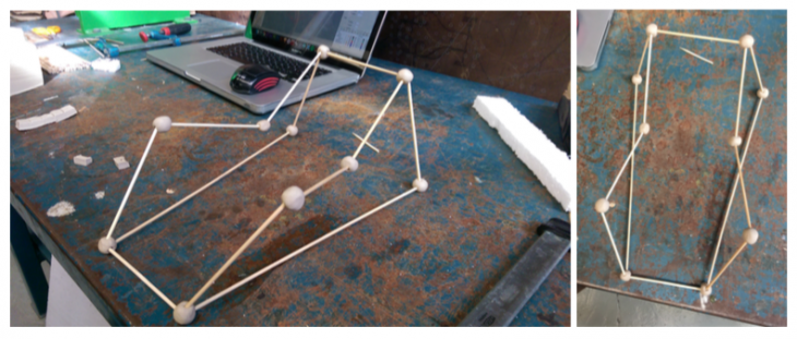
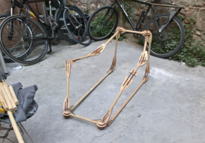
PHYSICAL_INITIAL MODEL
TECHNIQUE + MATERIALS

For the fabrication of our chair we decided to use laser cutting as the technique to cut the ply- wood at pieces. This pieces would then be interlocked to build each node geometry. We also got advantage of this by using the interlocking action to reinforce the bonds in between two different plane connections.
For our linear elements we used wooden broom sticks. As our concept was to create complexity in the nodes and simple elements elsewhere, we thought that broom sticks would do the trick.
KARAMBA_INITIAL SETUP
During the initial setup, the idea was to treat the structure as a com- position of a series of beams and shells. The shells would be used to display principle stresses, and from this a series of individualized and structurally optimized solutions would be developed.
However the problem at this point turned out to be in the communication of this geometry to the software and defining it. Therefore a different solution and therefore the workflow was developed.
KARAMBA_JOINT STUDY
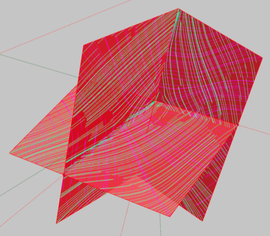
To understand how the forces would work in a simplified joint, such an individual was modeled and subjected to a series of forces that resembled ones in the real designed scenario. Both pulling (normal force) and moment forces were applied.
What was discovered in this experiment was that in such a situation, all the planes of the analyzed shell experienced completely different readings, and therefore the extracted lines of principle stresses, and later force flows have behaved in a rather unpredictable fashion.
The decision reached for further proceed- ing was to focus on dominant extremes (places with maximum tension/compres- sion/moment(in all 3 axis) and work on individual scenarios, allowing a more balanced and even distribution of forces engineering solutions. Therefore joint by joint we would study the behavior of forces, and working with sketches, simulations and prototypes, solve the imbalances.
KARAMBA_WORK SETUP
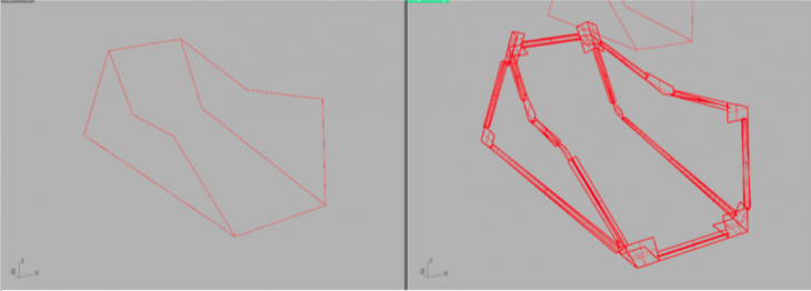
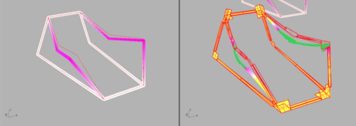
In order to perceive the corresponding reading of the forces, two digital models were created. Step by step they would be cross referenced for the readings.
The rst model showed a simpli ed situation that would be communicated as a solo beam scenario. These are lines mak- ing out the entire structure in scale. This model was used to analyse moments (Mx, My, Mz). These forces proved to be most critical in the project itself. The main challenge was not working with tension or compression, but stabilising the effects of moments.
The second model communicated a shell scenario of the same object. Instead of lines, here we had surfaces (shells). Since the focus of this project was to focus on the joints, these were modeled bigger than bars. Analyzing shells, we got a better understanding were are the key focus points of tension and compression, and also where we could take out some of the material.
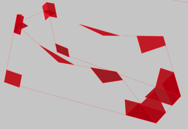
KARAMBA_GLOBAL ANALYSIS
From the primary global analysis of the situation, we discovered which parts of the structure would be subjected to major forces, therefore they would be the biggest test places for the stability of the built prototype.
This part was crucially important, if we would see reading that would be extremely alarming, this might have been the moment to modify the structural design of the entity. Fortunately we predicted correctly.
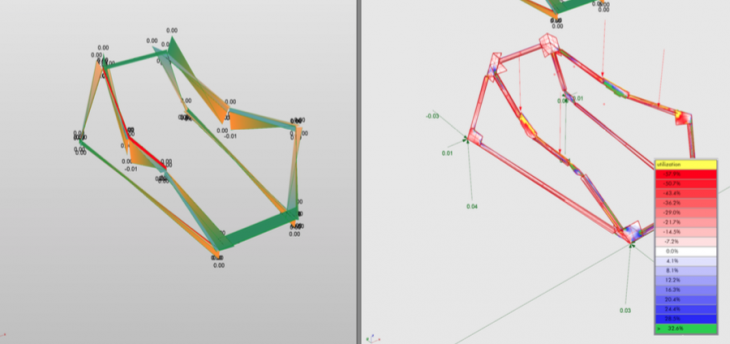
KARAMBA_DEFORMATION STUDY
The deformation study is a tool that told us how the structure will deform when subjected to force higher than its strength. The most vulnerable places there the arm suspenders, that when loaded, the structure would bend outwards, to the sides and down. From this and detailed global analysis, we knew that this will be the most challenging points that will require most focus.
After this step we proceeded to joint by joint analysis. Analyzing, sketching and looking for solutions, one after the other.
KARAMBA_JOINT 1
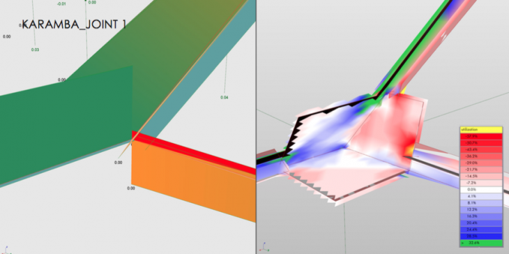
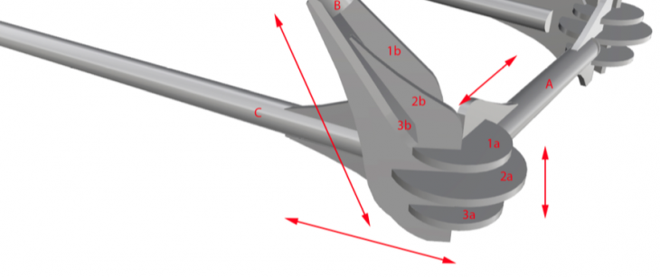
WHAT WE SEE: Joint 1 is a place where strong moments of 3 bars meet. These are two bars with high My moments (left and top) and a third with a minor torsion and a Mz. The joint will need to withstand these rotations.
From the utilization reading we see that there are some small areas of higher tension and others with higher compression. The imbalance, were on one side we experience tension, while on the other compression, often would mean a high moment focus. What is interesting here are the more neutral zones, represented as white. This is where we could get rid of some material.
HOW WE SOLVE IT? Due to the intersection of moments coming from different bars, the joining rings 1a,2a and 3a were introduced and improved (mainly in shape and spacing between them in z axis) in development prototypes until a solution providing enough stability was found. Since bar B was specifically delicate (in respect to being impacted by possible deformation), its contact with the node has become translated by 2 elements 1b and 2b (connected with plate 3b). By this the bending moment was more evenly distributed on the entire node. Lengths of the connections were influenced by the moment readings. The higher the moment, the longer the connection to allow the transition from the bar to the node be more spread.
KARAMBA_JOINT 2

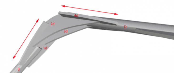
WHAT WE SEE? What is interesting about joint 2, is the changes of challenges we see. As moments My and Mz are not of dramatic magnitude, there is a new Mx torsion that is coming from the left.
However looking at the utilization, we see places of extreme concentration of forces. Compression on the right is reach- ing a high, but right behind it we see glimpse of extreme high tension. An interesting sign that can communicate the bend- ing moment changes on this branch of the structure. Also we have balanced zones visible in white on the top, meaning they are not used to conduct pulling or pushing.
HOW WE SOLVE IT? Due to the high concentrations of force, plates of transferring (1d and 4d) have been elongated and two perpendicular plates 2d and 3d have been introduced to allow a stable scenario and transfer of bending. The two plates have also divided roles between each other; 2d handles major compressions while 3d handles major tension. Since compression is focused on lower parts of the plate, it has been lowered and the useless top trimmed of. On the opposite, the 3d has been moved slightly high- er, since this was the place of major tension readings. In this case, the neutral areas were shortened and eliminated, providing a more optimal structure.
KARAMBA_JOINT 3
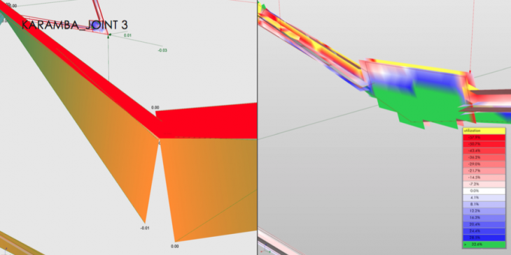
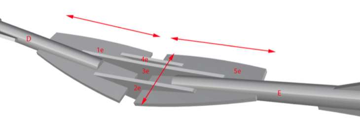
WHAT WE SEE? Joint 3 is the place of maximum moments observed in the entire structure. Not only a major My but also two torsions meeting being translated from one bar to the other. Further- more, this is the place most likely to deform if the strength of the structure would be exceeded.
In terms of the utilization; we see practically on the entire segment, elements of extreme tension and compression, one directly over the other. The delicate aspect is that this imbal- ance, the torsion, could break a possible joint if not designed carefully.
Again we see the two force on opposite extremes. Tension focusses on inner lower parts of the plate, while high compression on the upper outer part of the plate.
HOW WE SOLVE IT? Due to the long zone of concentration of tension and compression points, as well as the moments being at the all time high (in terms of all moments visible in this structure) the area of contact between the rod and the node is the longest. This allows easy distribution of forces, so no single focus point would become risky for failure. In order to deal with the moments, 3 plates were introduced 2e, 3e and 4e. The role of the plates is to provide super stability for the component. The dimensions and placement of the plates is based on utilization readings.
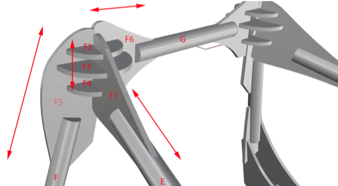
KARAMBA_JOINT 4

WHAT WE SEE? Joint 3 is the place of maximum moments observed in the entire structure. Not only a major My but also two torsions meeting being translated from one bar to the other. Further- more, this is the place most likely to deform if the strength of the structure would be exceeded.
In terms of the utilization; we see practically on the entire segment, elements of extreme tension and compression, one directly over the other. The delicate aspect is that this imbal- ance, the torsion, could break a possible joint if not designed carefully.
Again we see the two force on opposite extremes. Tension focusses on inner lower parts of the plate, while high compression on the upper outer part of the plate.
HOW WE SOLVE IT? Due to high moment forces and concentrated points of either tension or compression, F1 and F5 are longer and distribute from the forces on F2, F3 and F3. These 3 rings pro- vide great stability when in series. Also due to their dimensions, they allow very stable setting. This joint resembles joint 1, and was developed basing on the observations of the 1 joint. In contrast it deals with higher moments on 2 bars (E, F), this is why they are longer and have more material around the place of contact with the rings.
KARAMBA_JOINT 5
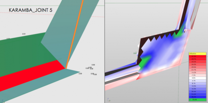
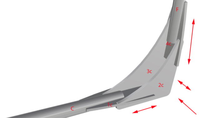
WHAT WE SEE? Joint 5 experiences some torsion and both a My and Mz. The magnitude of these moments is not major (unlike it looks on the image) however again we notice the spots of extreme tension and extreme compression on the outer side. This situation is familiar since it resembles closely joint 2. The possible behavior of this node is an outwards movement when loaded, however for ease of computation, this scenario was
HOW WE SOLVE IT? Since from the utilization we know there is no major zone of either compression or ten- sion, there is no need for a major elongation of place of contact with bar. However due to moments, plates 3c and 2c are introduced. These two plates together block possible bending and deformation that could result.
KARAMBA_TEST

After the act of design of each joint was completed. As the prototype was assembles, another analysis was made to verify the efficiency of the solution proposed. The reading proved a balanced scenario with no major places of focus of either tension or compression.
As for the displacement, the reading of such a possible behavior has been made drastically smaller. The zone has remained marked as a more delicate material, however the behavior of simulation of load application proved to be different.
Unfortunately, for such a complex model, obtaining moment readings proved to be much harder and inaccurate.
SOLUTION FINDING
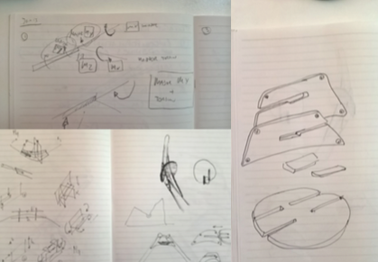
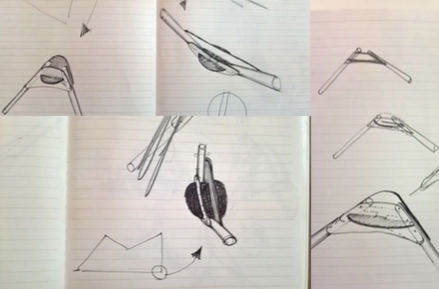
The process of solution finding has usually started with speculations how the structure will behave, trying to understand the dominant tendencies in the behavior of the entity and then looking closer joint by joint.
After understanding the key functions of each element, the real challenge was to find a geometry that would solve the problems; if it was rotation of one of the elements that would be driven by moment or tension and compression.
For each of the joints sketches were made, one after the other to find optimal situations that would be coherent with the overall aesthetic.
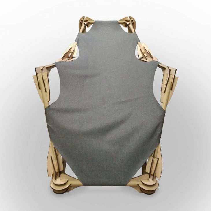
ASSEMBLY
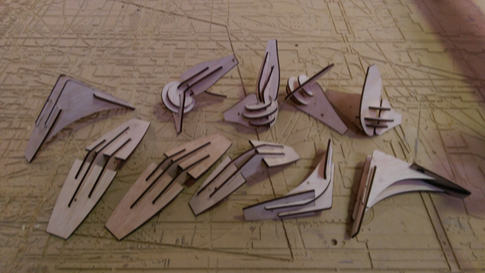
After all joints were assembled together, than one by one rods were modi ed to respect the designed angles and provide necessary stability.
In order not to be confused during laser cutting, each element received an engraving with its individual lettering, this helped to save time and for assembly accuracy.
CONCLUSIONS
HARDWARE: The aspect of prototyping proved to be a bigger challenge than we expected at first. The communication between the digital object and the physical means of obtaining it as planned.
Due to difficulty in assembling small and precise components, we had to revise the design and modify it to work in terms of working with force analysis, but also be possible to put together by hands.
We expected to create a object more stable than we have. This was however not the result.
SOFTWARE: Karamba proved to be a very surprising tool with its possibilities, however we also discovered some limitation and errors. The way of looking on objects using it is very unique and extremely useful. Also its results should be verified before production.
Rhino’s advanced possibilities turned out to be of great values, translating a geometry from a surface to mesh, extracting points and other operations that allow to save time and be very precise.
DIS SEMINAR: One of the strongest experiences working on this chair, has been an introduction to a new perspective of looking at physics, and reworking towards a “pure” solution. This class in general has allowed us to perceive structural design and how we can work with it differently, and this is fantastic.
Team: Marcel Dawid, Javier Montalvo, Cesar Arroyo, Francis Redman.
Tutors: Manja van de Worp, Abdullah Ibrahim.