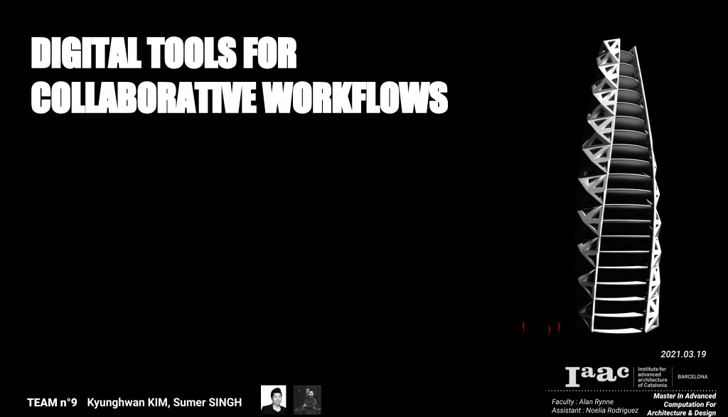

The Collaborative tower project by our group for the Collaborative Workflows course was an exercise in utilizing the potential of Speckle in order to collect data streams in a Revit project. By starting with a basic bounding box and allowing that to evolve from a conceptual massing to panel details and floors inside the Rhino/GH environment, we were able to successfully propagate the creation of Speckle streams while simultaneously developing our project. The floors were assigned as Revit objects inside Grasshopper, and when the stream was downloaded inside Revit, it automatically created the floors, assigned floor elevations, and also created the floor plans. We found this to be the biggest advantage in the creation and detailing of a project using a collaborative tool such as Speckle.
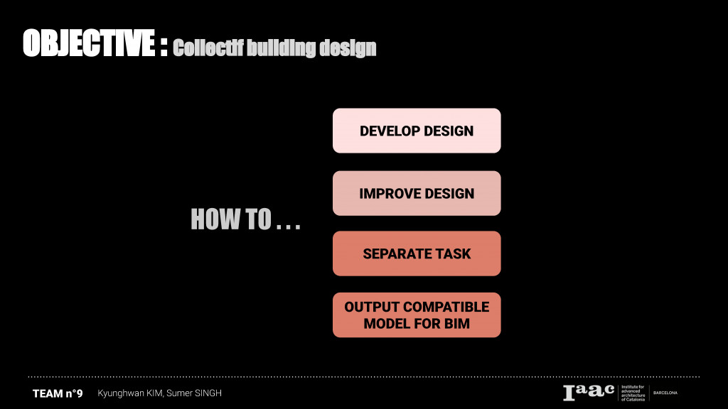 The main question of this project was how two architects from two different countries can effectively improve and develop a building design in collaborative manner. But also, we thought about how to separate tasks for separating effectively Speckle’s data streaming.
 Therefore, our scenario for the workflow was to separate by Facade design for one architect, Kim, and then floor height, panel and window design is taken place by another architect, Sumer. Their data were exchanged very fluently by ‘Speckle’ tool. Two streams of facade design from Kim and panel & window design and floor from Sumer is received by one center data which is connected with Revit. We could work in Revit to make more detailed drawing, but also it could be sent to our future collaborators since Speckle is possible to send form Revit to Revit. In the end, we will receive 3 different data streams from structure engineer, mechanician and electrician. These datas will be applied in our deatail data and center data for architecture to update.
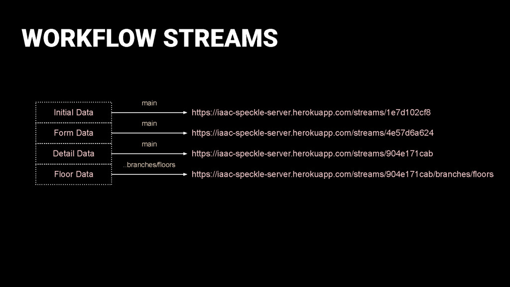
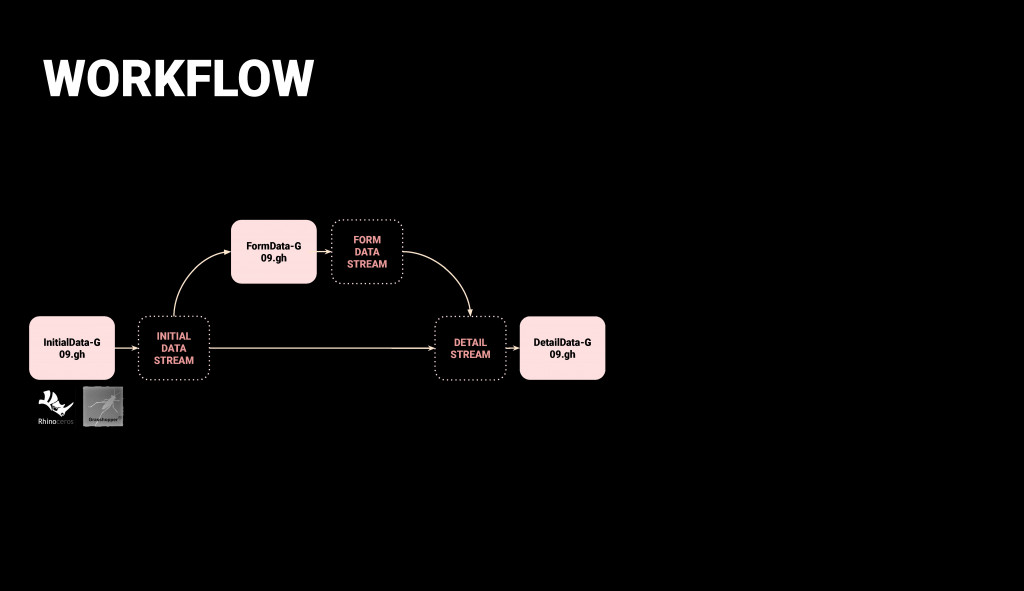
We subdivided the workflow into the streams as shown in the image above: Initial Data, Form Data, Detail Data and the Floor Data that was actually a branch of the Detail Data.
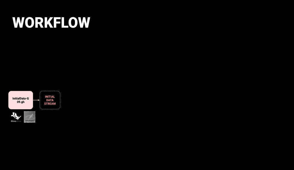 The initial data stream nodes consisted of the topography of the site, the plot outline of the bounding box, and the modified overall volume within which we could create the project.
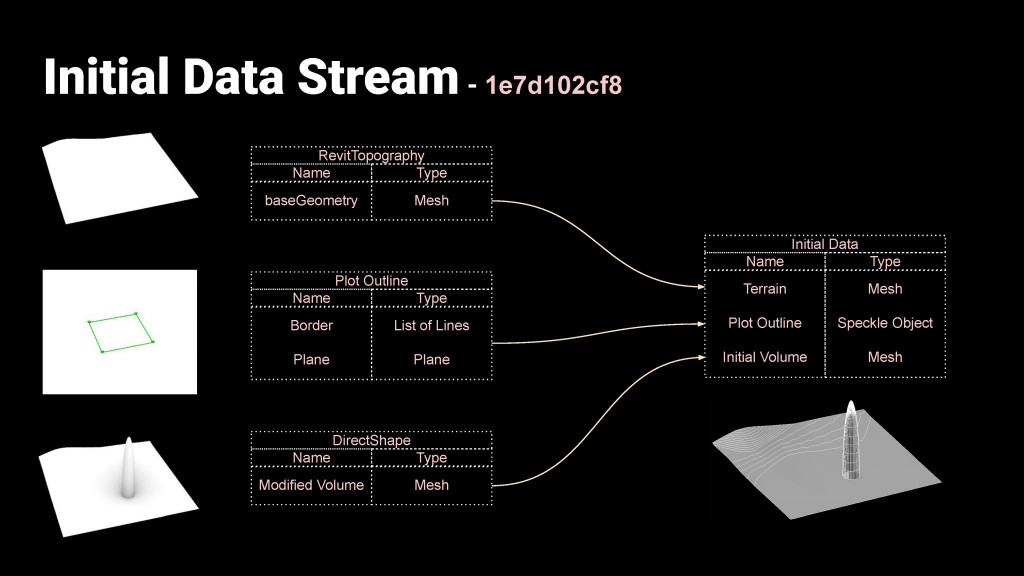 These 3 items were the output for the initial data that was sent to the form data and the detail data streams.
 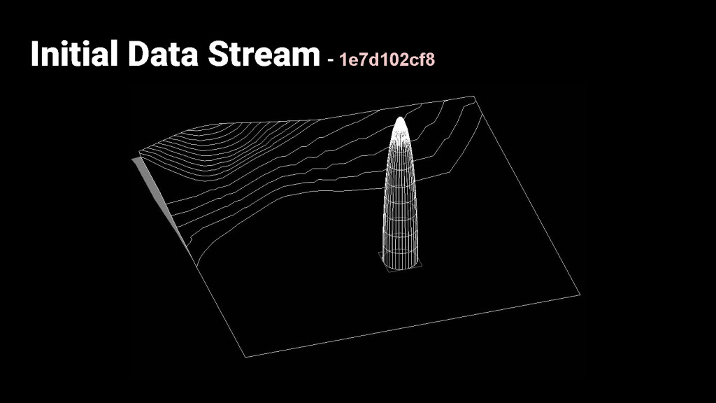 Here is our first data stream sent to one collaborator.
 The first mesh tower design was received by the collaborator and modified by using its original geometry information such as ground floor surface and height.
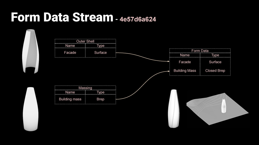
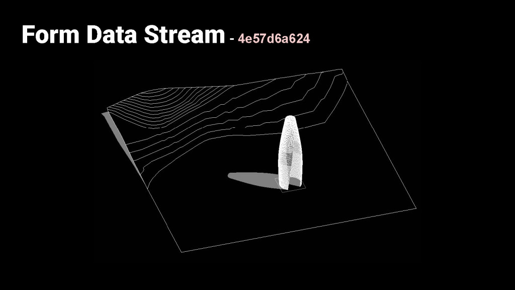 The outer shell and massing were created using the initial data as input. The outer shell would be used for the facade penalization details and the massing would be used for the floor plates.
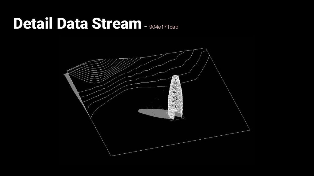
 The detail data stream collected the site and location of the project from the initial data stream. In addition the form data stream provided the outer shell as input for the creation of the facade details. The detail data stream output was the panels and the windows which was sent to the main Revit file for the merging of the streams.
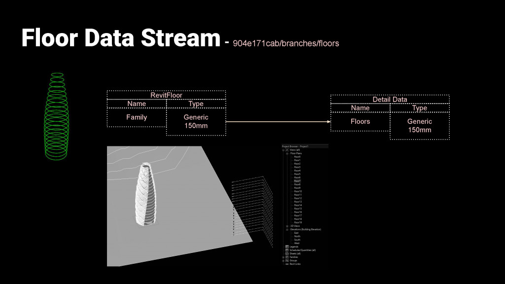 The floor data stream was created as a branch of the detail data stream. In this case, it took the massing of the form from the Form data stream, and assigned floors as Revit objects inside Grasshopper. The big advantage of doing this was that when the floor data was downloaded in Revit, it created and assigned the floors along with creating the floor plans automatically.
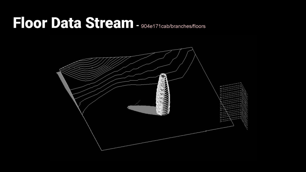
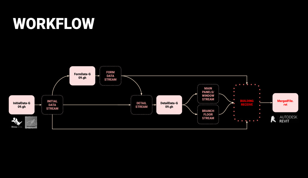 In conclusion, the final workflow started with the initial data feeding into the form data and detail data, which finally fed into the Revit File that received all the streams. In our particular case, we subdivided the tasks based on the above streams and collected the information in Revit before finalizing the project.
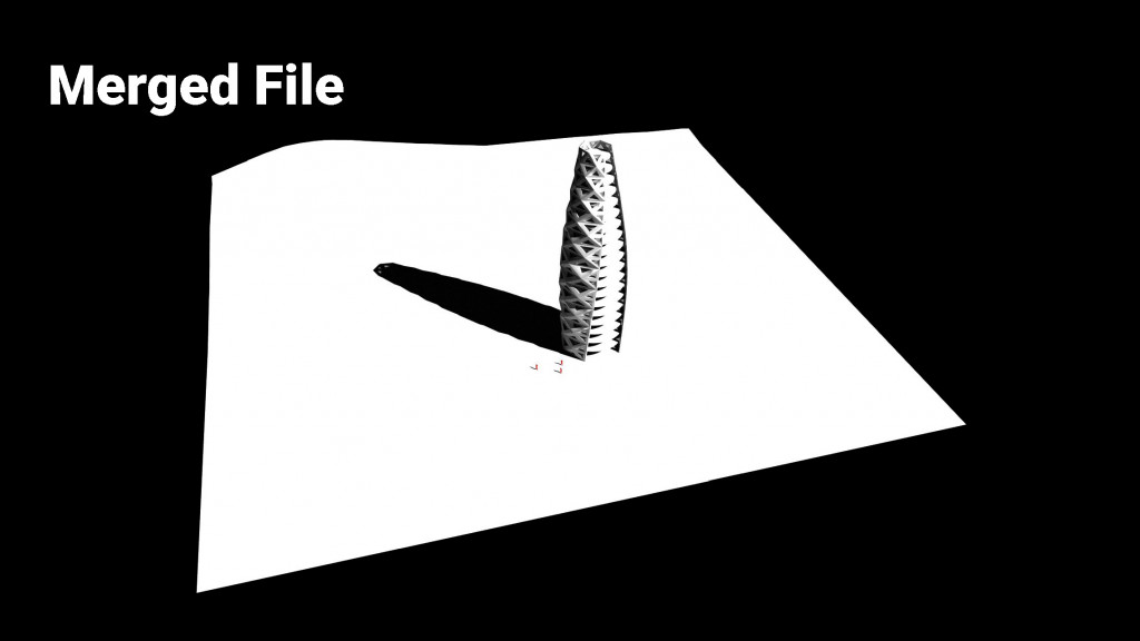
Students: Kyunghwan Kim, Sumer Matharu
Faculty: Alan Rynne
Support: Noelia Rodriguez Garcia