Seleno-BIO Habitat is a residential project on the Moon, based on the concept of modular growth. One of the clusters of residential units is taken as a case study to present the collaborative workflow within a team. The project was realized by 2 architects and an engineer, sharing the information about geometry and project parameters between Rhino, Grasshopper and Revit using Speckle.
This blog post is focused on the collaboration workflow of the project. The full project presentation can be accessed at THIS LINK
//TOOLS
The collaboration platform for the project was Speckle, which enabled integration of models in Rhino, Grasshopper and Revit using a cloud-based environment.
//GOALS
The goal of planning the collaboration process was to allow a good information flow between different members of the team and integration between the different software. In order to take advantage of the benefits of each software, Rhino and Grasshopper were used in the early stages of the design, allowing for parametric definition of a complex form geometry. Revit proved to be a suitable choice for creating a full 2d documentation of the building as well as quantity schedules, which was the end deliverable required for the project.
// WORKFLOW
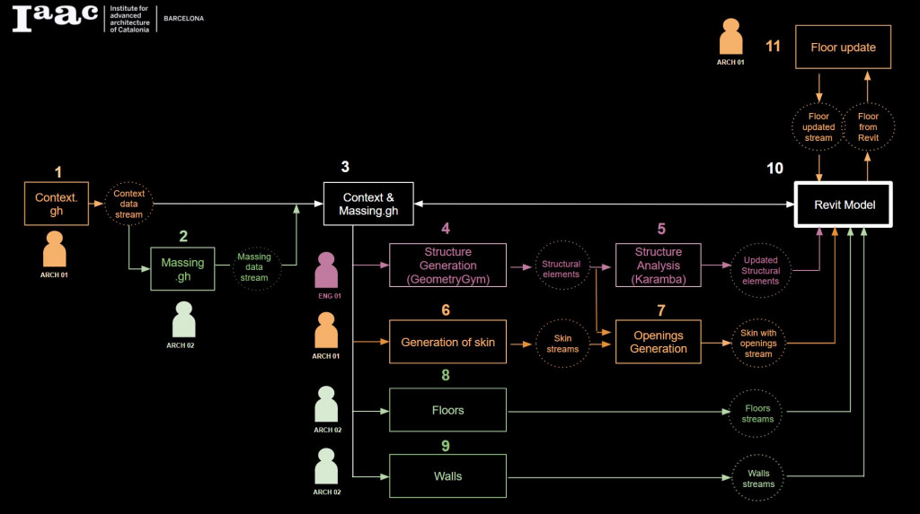
The following diagrams explain the collaborative workflow adopted in the design. It assumes interaction of 2 architects and 1 engineer and has 11 steps. The process facilitates collaboration between the team members and feedback loops allowing for project updates. The result of each step is a Speckle stream.

//STEP BY STEP
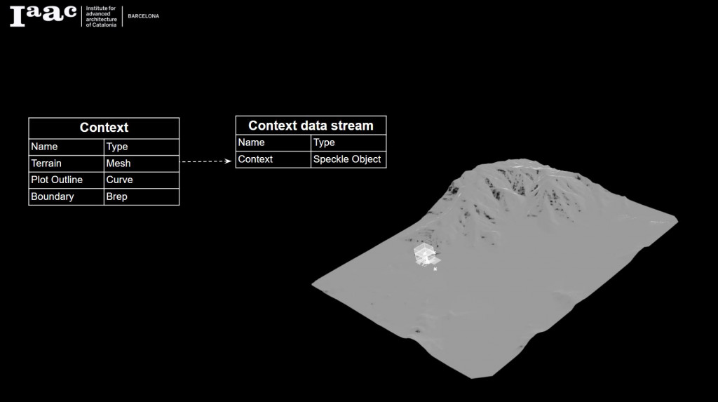
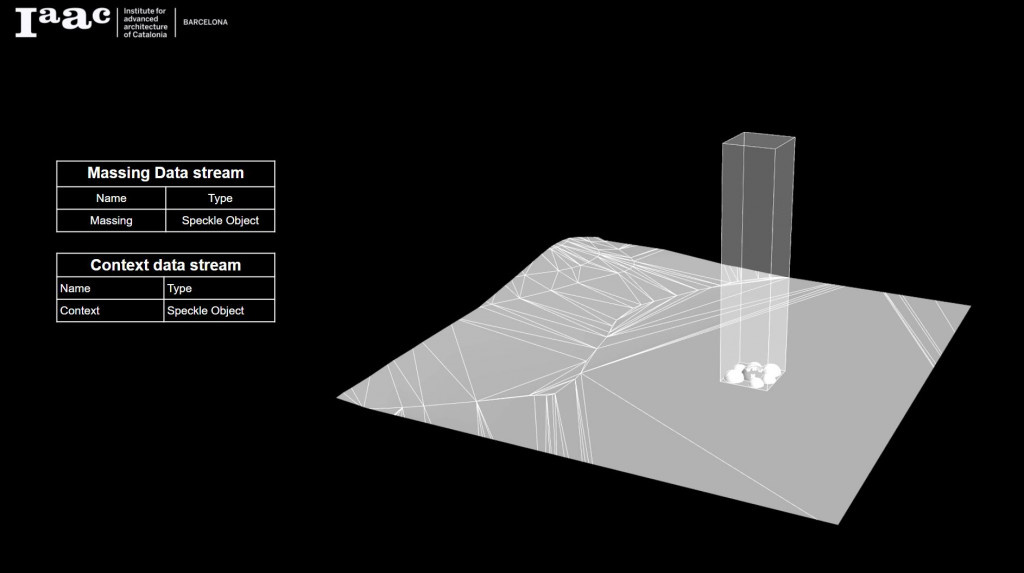
The first step was to create a file with project context. The terrain, plot outline and boundary volume was sent in a Speckle stream to Architect 2.
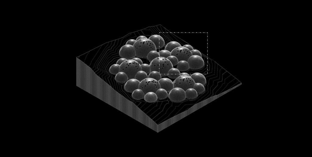
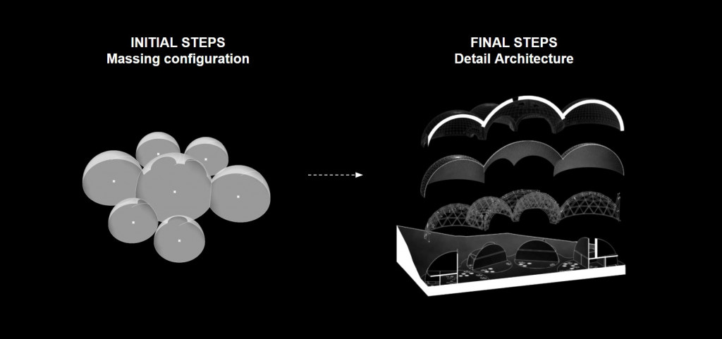
In the Seleno-Bio-Habitat project, massing was created based on the growth algorithm that added clusters of residential units connected with one common area module. In the case study one of the clusters was chosen. The cluster was composed of modules of 3 different sizes. Data structure organization was created to group units of the same size together. Each of the unit objects was defined by a center point, surface of a dome and a corresponding dome radius. The final information was passed as a list of unit objects.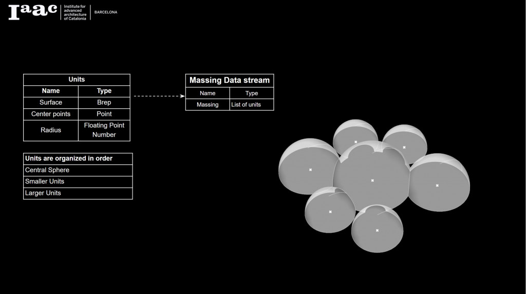
Next step was to combine the massing and the context in one Rhino file.
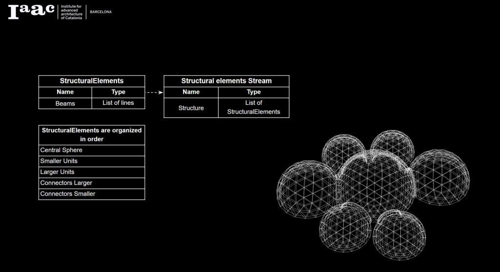
Based on this information, the engineer started preparing the structural element model. GeometryGym plug-in for Grasshopper was used to generate the geodesic dome structure. The structure is composed of 2 layers to allow for hosting a green wall panel in between. The domes were connected with a 3-d truss arch structure. All of the elements were sent for further analysis as a list of line elements, grouped together with respect to the size of the units.
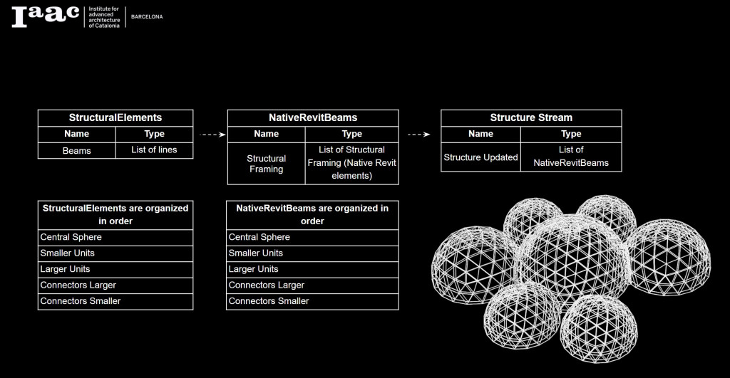
The next task for the engineer was structural analysis using Karamba plug-in for Grasshopper. Line elements from the previous step were used for the analysis and as a result, an adequate cross-section of a beam was chosen. This cross section was assigned to a line element using CreateSchemaObject Speckle Component, which created a list if native Revit beam element, ready to be received in Revit.
In parallel, the architect 1 was working on creating the outer layer of the modules. It was generated in Grasshopper and transferred as a solid, grouped according to the size of the dome
.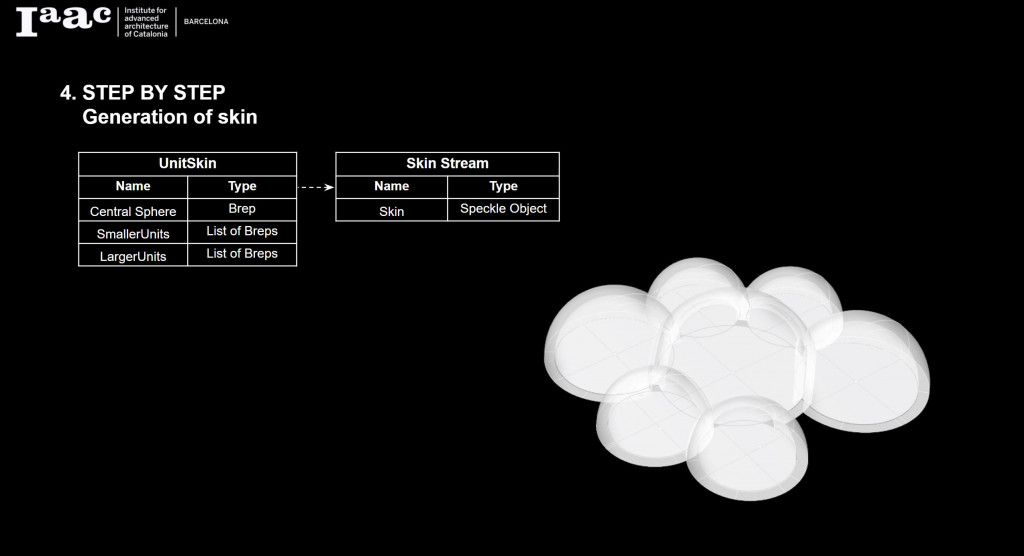
After creating the skin, openings were added to the central module. Based on the previous geometry of the units, the openings and the new skin of the central dome, Revit elements were created. They were generated using CreateSchemaObject Speckle Component, creating DirectShape geometry, which prepared Generic Model Revit objects of type Wall and type Window.

Another step was to create the slab elements. Native Revit Floors were generated based on the outline and assigned a Structural Floor category of type Generic Floor 300 mm.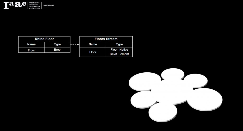
Internal walls were generated in Rhino by Architect 2. Due to the irregular shape of the walls, they were transferred into Revit as a Generic Model of type Wall, rather than as a native wall family.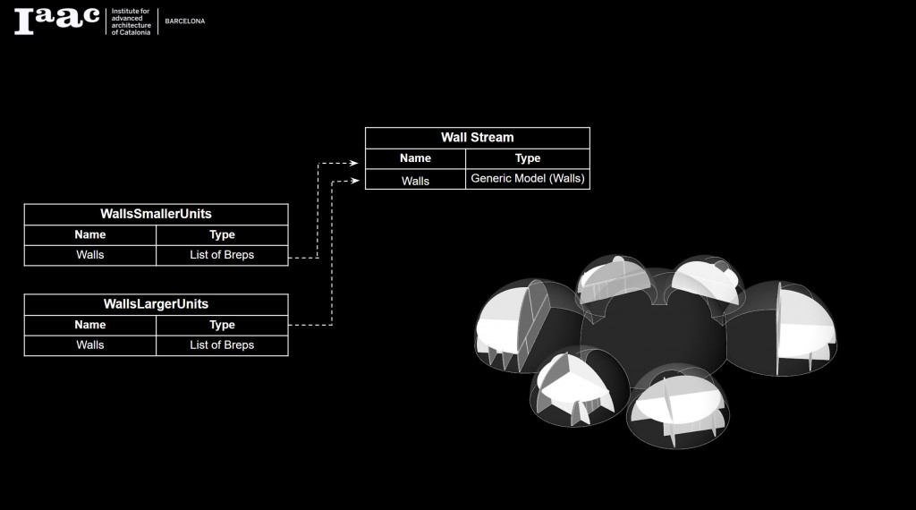
//FINAL MODEL
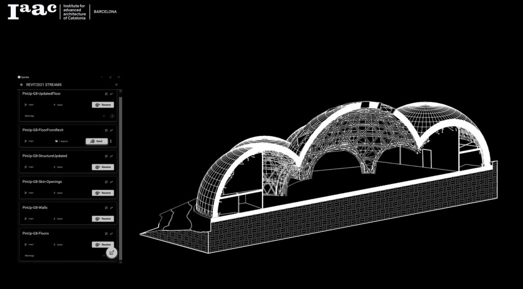 The final outcome was a Revit model that integrates all the geometry created in the previous steps. Having a BIM model allowed for easy generation of documentation and quantity schedules. It can be also used for multidisciplinary coordination, clash detection and construction sequence planning.
The full documentation can be accessed using THIS LINK.
//UPDATES
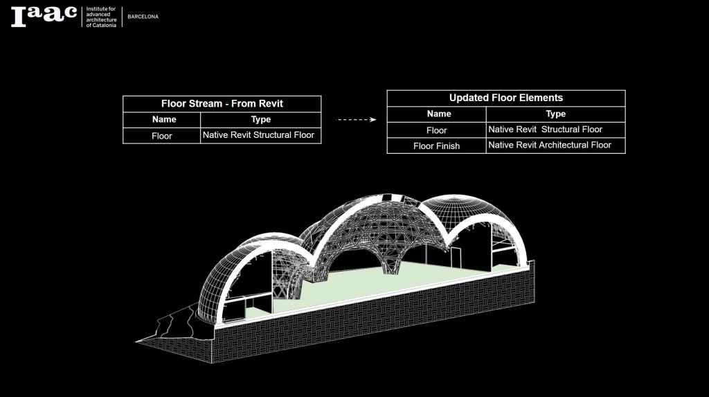
During each design process there is a need for updates of the geometry or the information. To account for introducing changes to the project, an additional step was included, where a geometry from Revit is sent back to the Rhino model. In this case study, an example of creating an additional layer of floor finishes was proposed. Based on the floor geometry received from Revit, the Structural Floor element thickness was modified and an additional finish layer was added. The stream including the modified Structural Floor element and new Architectural Floor element was sent back to the Revit model.
Seleno Bio-Habitat is a project of IAAC, Institute for Advanced Architecture of Catalonia developed at Master in Advanced Computation for Architecture & Design – MaCAD in 2021 by students: Aleksandra Jastrz?bska, Abed E. Badran, Jonathan Hernández López and faculty:Alan Rynne & Noelia Rodriguez
