// CONCEPT
A parametric, cuboid grid can be fabricated with the KUKA robotic arm utilizing simple wooden pin connections. Creating a simple joint of three wooden battons, a parametric cuboid grid can be created. By altering the length of the wooden battons, the density of the cuboid grid can be controlled, resulting in shifts in translucency throughout the structure.
// FABRICATION PROCESS
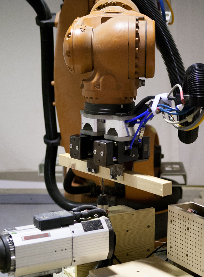
The KUKA robots first picks a 38 x 1000 mm Catalan wood (softwood) batton from a custom built feeder and cuts it to the designed length using a table-mounted circular saw.
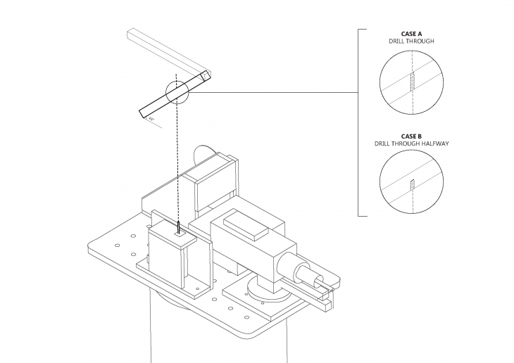
 After cutting, the KUKA arm passes the stick into a manually controlled table-mounted drill. Specifically, the on-off switch of the drill is controlled outside of the KUKA room. Depending on the connection detail, the drill either drills through the entire batton or drills halfway.
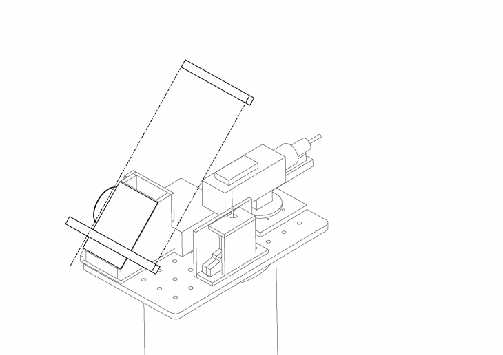
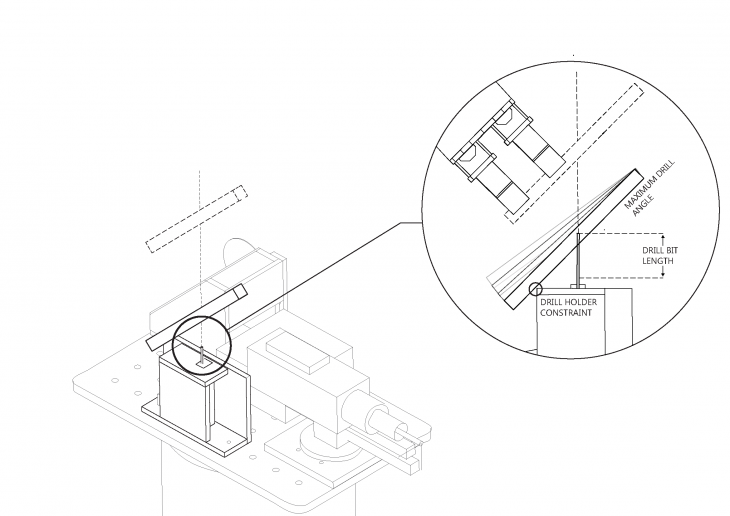
The maximum angle the batton can be held at is constrained by the KUKA arm itself, the position of drill holder (fastened onto the table) and the drill bit length. If the batton is held at an angle which is too steep, it will collide with the table prior to drilling.
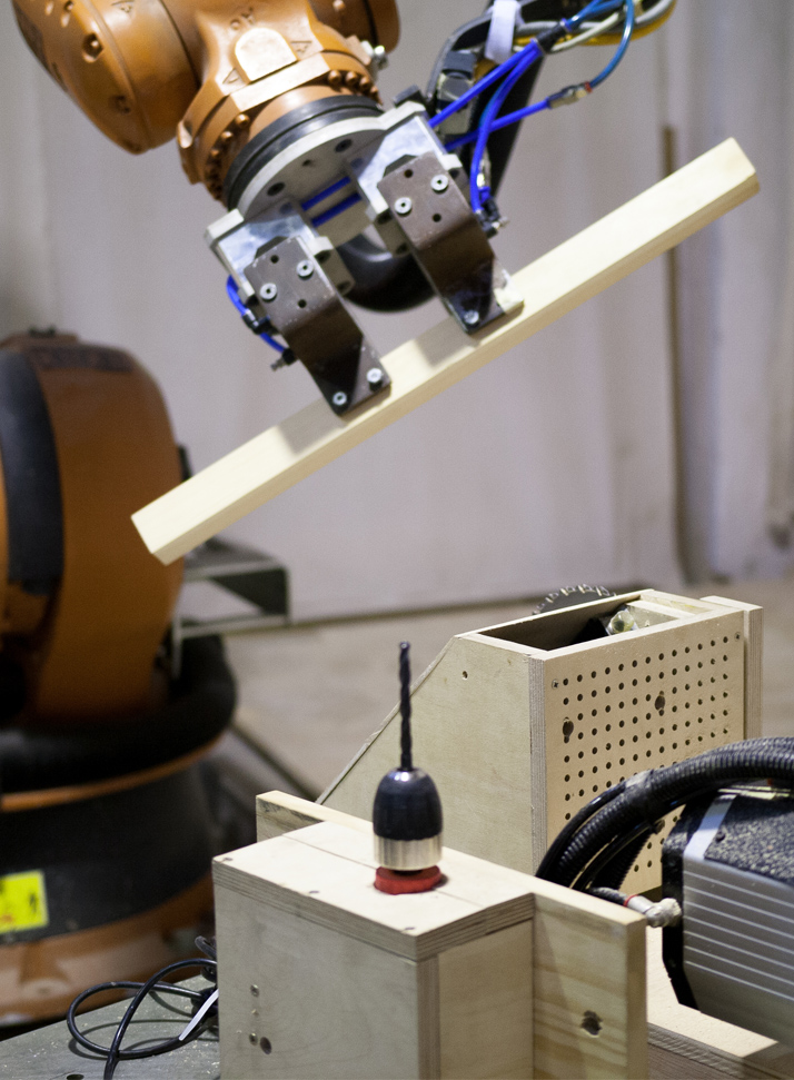
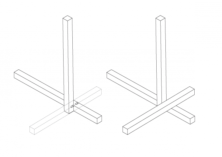
After a hole is drilled into the wooden batton, the KUKA robot passes over a grid of vertically oriented wooden pins which were placed prior to beginning the fabrication process. The KUKA descends, lining up the drill hole with the wooden pin. The force of this downward motion, pushes the wooden pins into the drill hole. However, half of the wooden pin is left exposed.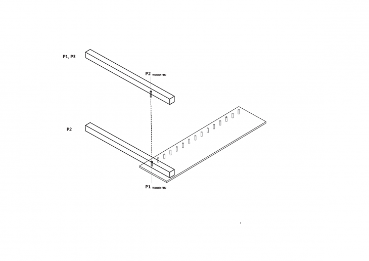 The wooden stick is then placed into position on the ground. Subsequent steps are similar; however, the wooden batton with a designed female connection does not require a wooden pin. Instead, as the KUKA places the subsequent sticks, the female and male connection is pushed together.
 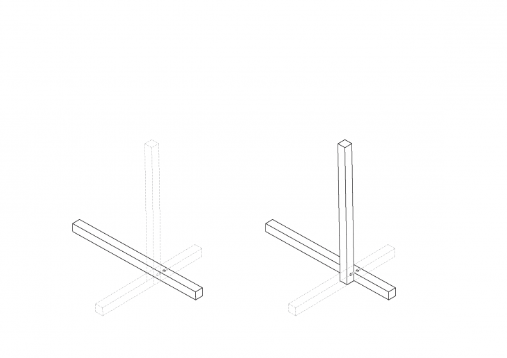 As a result, a completed module is self-assembled entirely by the KUKA. Additional modules can be assembled together, by hand, upon completion.
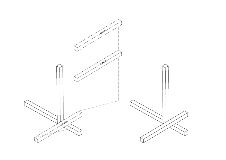
// DETAILS
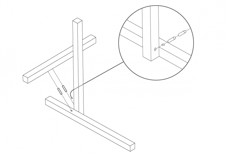
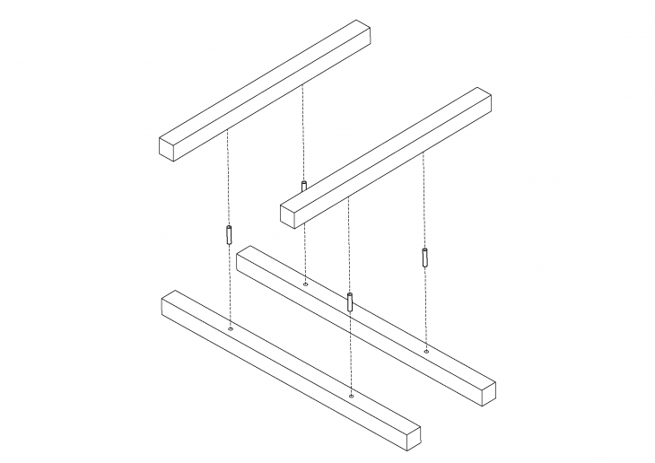
The main connection detail explored was a wooden pin connection. By using the KUKA arm to pre-drill and place the wooden battons, parametric modules could be built one-by-one and then assembled.
The main connection detail explored was a wooden pin connection. By using the KUKA arm to pre-drill and place the wooden battons, parametric modules could be built one-by-one and then assembled.
// MOVING FORWARD
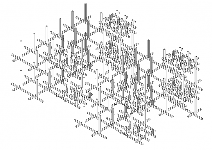
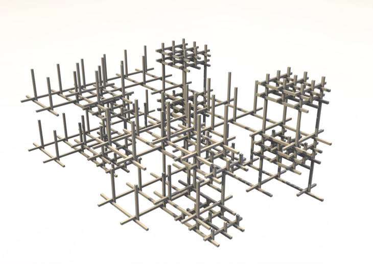
Building off of a grid, the modules can be attached together and assembled into a larger structure. The orthogonal grid can be altered at any time to
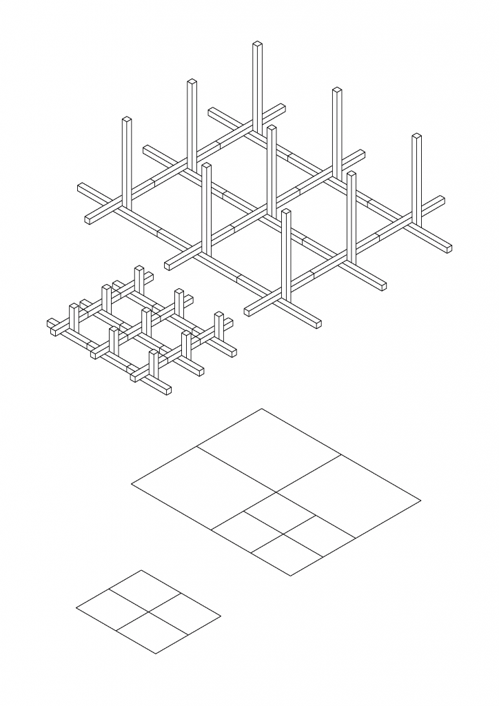
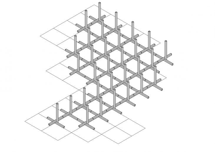
Speculating on the final form shows how density can be controlled throughout the structure.
 // VIDEO
To test the possibility of using wooden pins to connect wooden battons, a “proof of concept” module was designed. The KUKA was programmed to cut, drill and place the wooden battons. Group members placed the wooden pins prior to placement.
The following video showcases the robotic fabrication process of the “Proof of concept” module shown above.
The KUKA robot movement was first programmed and simulated using the KUKA prc plugin for grasshopper. The simulation was used as a design tool to ensure no major problems would occur when played in reality. However, as we came to realize, the simulation does not show all potential problems and numerous iterations had to be tested.
Cuboid Grid is a project of IaaC, Institute for Advanced Architecture of Catalonia developed at Master in Advanced Architecture in 2016 by:
Students: Nikos Argyros, Pedro Arroyo, Connor Stevens, Mercedes Swiecicki and Christopher Wong
Faculty: Alexandre Dubor, Djordje Stanojevic
