**project developed as part of MRAC Hardware II Seminar 2019/2020 // the project and all its associated files -> click to access gihub post
Remote control is a live controller for 6-axis robotic arms, operating via a live communication between the controlling device and the robot. The project has as objectives the development of an IMU-enabled controller device interfaced with the robot through making use of the real-time data flow provided by Machina Bridge.
OVERVIEW
Inially, the project started with the development of an IMU strip, with the goal of retrieving the live position in space of the sensors and calculating the real time movement of the strip digitally. The target application was to measure object’s dimensions and features by calculating the amount of deformation encountered in the IMU strip, reported to a pre-determined ground truth value for all the sensors.
Later, the idea became valuable for robot live-control applications, where one IMU could be used as an attractor point, or where multiple IMUs could provide custom joint controll for the 6axis.
HARDWARE
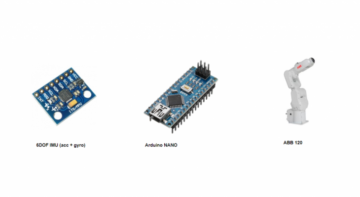
Throughout the development of the project, the hardware used constitutes of 5 low-price IMUs, an arduino nano and the ABB 120.
SOFTWARE
Digital workflows used for development:
- Arduino- Processing
- Arduino- Firefly-Grasshopper
- Arduino- Firefly- Grasshopper- exMachina
PROCESS
/ CIRCUIT A -test
- simple circuit (1 IMU)
- outputs Acceleration & Gyroscope data
- Arduino to processing
Output data visualised in real-time in Processing:
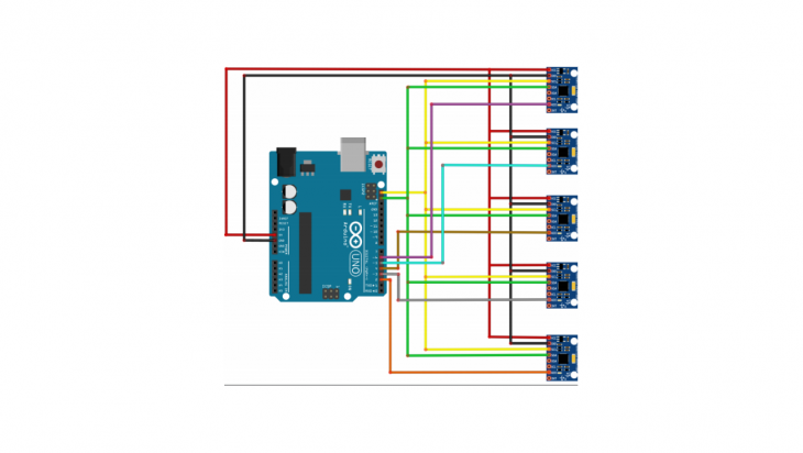
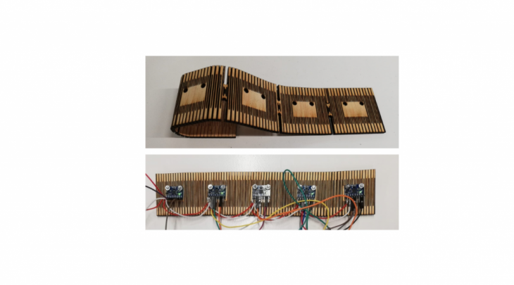
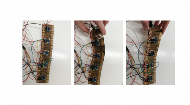
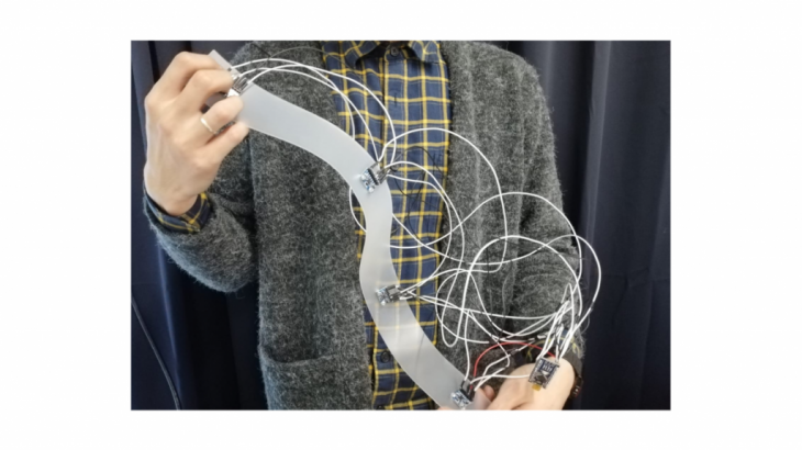
/ CIRCUIT B – IMU strip
- 5 IMUs connected to Arduino chained via I2C protocol
- Arduino Uno
- Visualised in Arduino Serial Monitor
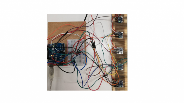
First iteration of the IMU strip:
Arduino Serial Monitor first readings:
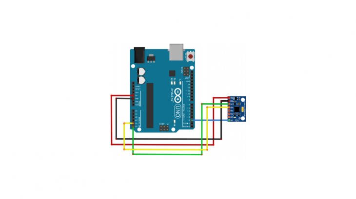
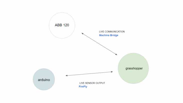
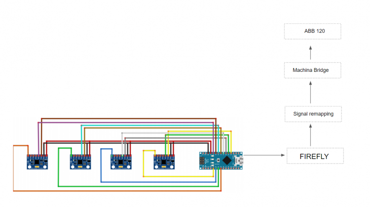
/ CIRCUIT C – interfacing with the robot
The communication protocol is set between Arduino and Grasshopper via the Firefly plug-in, reading and interpolating data. The data is then stabilized in Grasshopper and sent to the ABB 120 in real-time via Machina Bridge.
- circuit diagram:
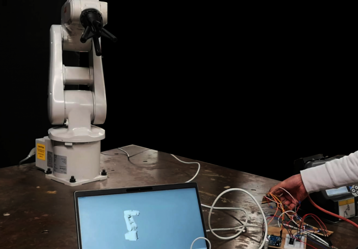
- devices:
IMU attractor point controller
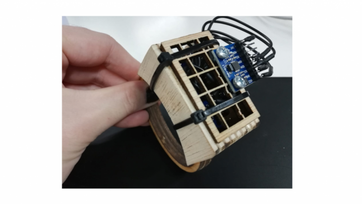
The hand-held device acts as an attractor point for the robot in jogging mode, interpolating the robot position based on the live sensor readings of the IMU position.
IMU strip
The device is supposed to enable individual control for each one of the robot’s joints.
APPLICATION