
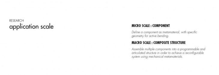
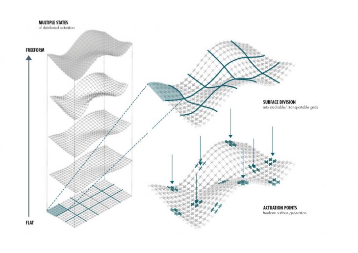
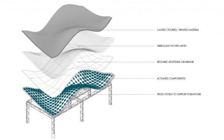
METAFORM is a research project which proposes a reusable fabrication method for casted freeform surfaces based on dynamically reconfigurable auxetic structures. The main objective is to produce a standardized component system that is able to deform upon the application of local force and as a result globally propagate controlled deformation across the system. This process enables for the transition from a flat state into a range of complex freeform surfaces, making use of distributed actuation with minimal force applied.
The project explores the use of distributed actuation within a meta-material system, in an attempt to achieve an adaptive reconfigurable structure with multiple stable states. The use of materials which behave according to their structure as opposed to their inherent properties allows us to have control over the material system, the properties and behaviour of which can be controlled and manipulated by making minor alterations in the material’s design, resulting in an optimized mechanical behaviour of the meta-material.

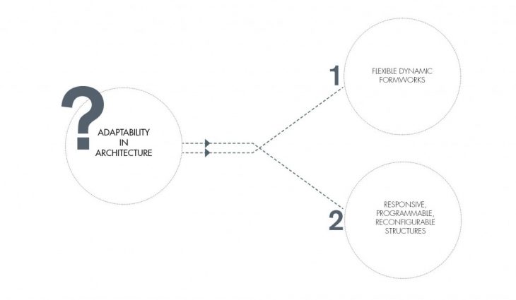
The subject of adaptability in architecture is tackled via two different approaches. The first approach is proposing a flexible dynamic formwork system with direct applications in the construction industry. The second approach is exploring the possibility of responsive, programmable structures which directly engage with the user and usage patterns resulting in a dialogue between form and user behaviour.
Recent studies in the field of material science and bio-mimicry have led scientists, engineers and architects to find great inspiration in mechanical behaviour of materials, as well as interesting geometrical compositions at nano-scale allowing for a more organic approach to adaptability and efficient performance in architecture.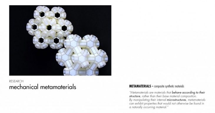
Metamaterials are materials which behave according to their structure rather than their base composition.
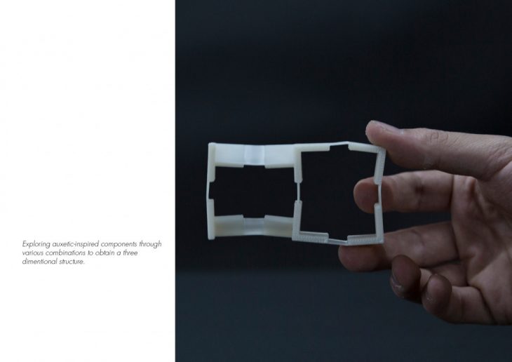
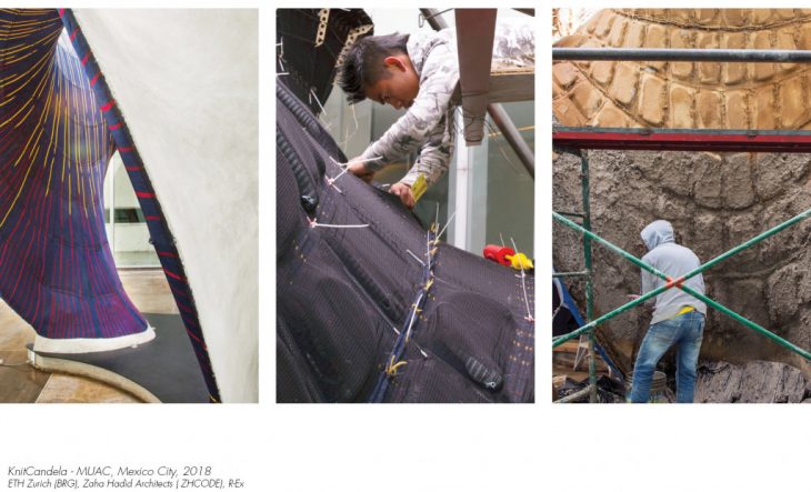
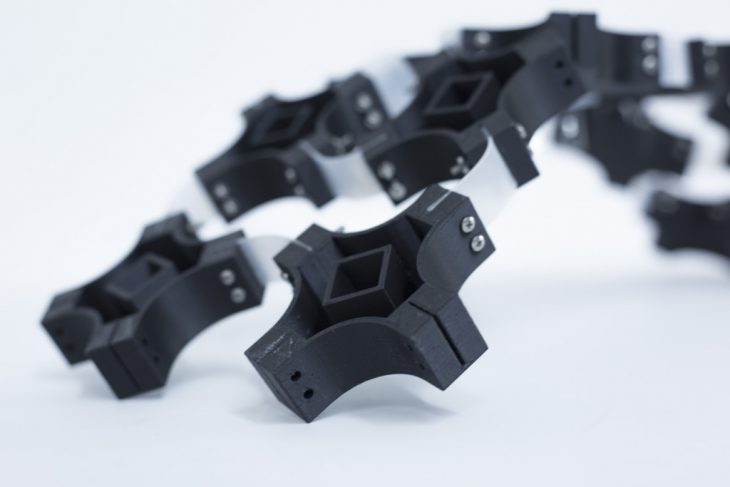
This research utilizes a component-based system able to propagate deformation from the actuation of a single component to the entire system, eliminating the need of multiple actuators, thus aiming towards a more efficient responsive structure. The system incorporates an active bending principle consisting of rigid bodies with shifted elastic joints found in “KinetiX”, a research project describing a group of auxetic-inspired material structures that can transform into various shapes upon compression.¹
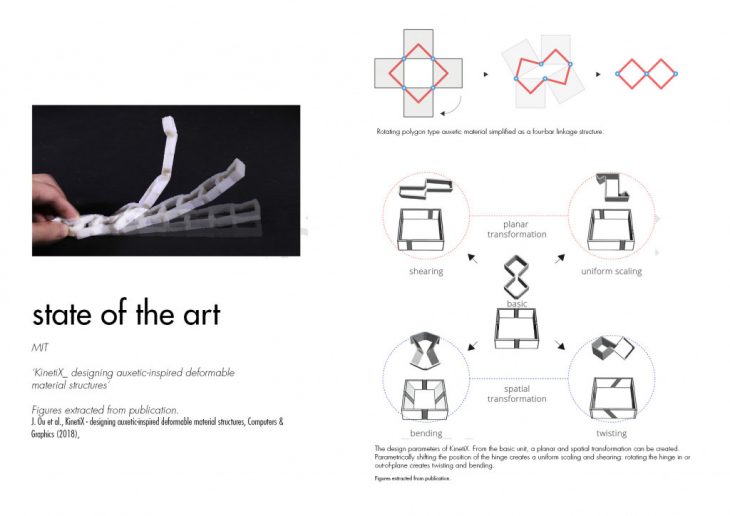
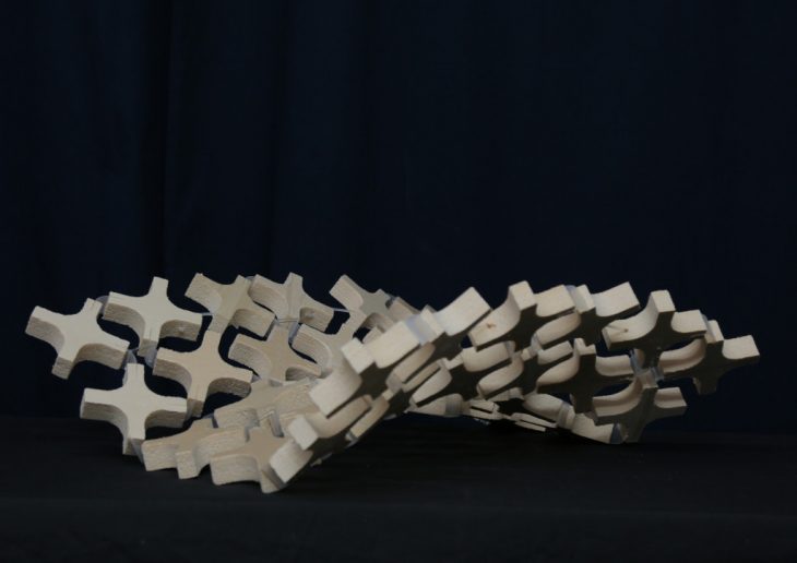
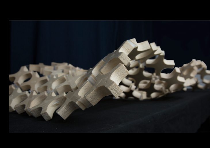
By recreating the aforementioned research we are able to produce systems comprised of deformable spines which result in a formal exploration of various achievable forms and structures.
RECONFIGURATION PRINCIPLE
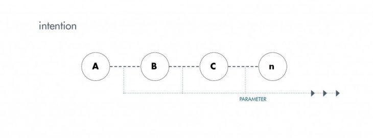
The research is based on the intention of developing adaptive structures which can achieve a gradient of stable states. The desired structures should be able to make the transition from state A to state B,C,D…,n, and return to their original form, in a repeatable reconfiguration loop.
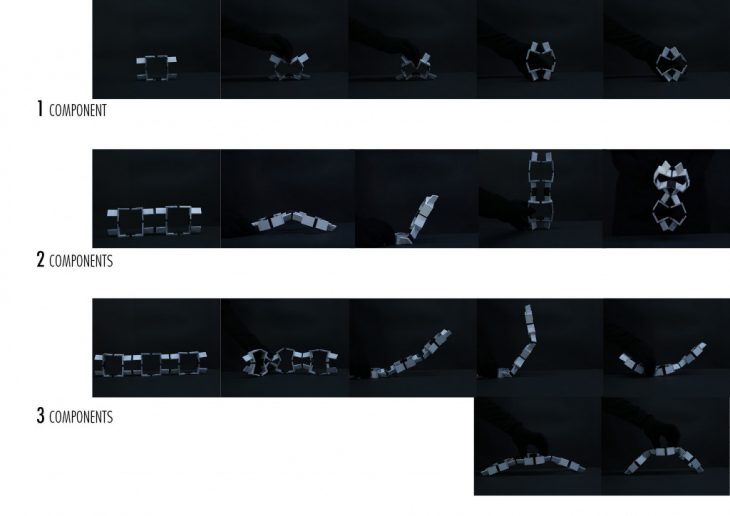
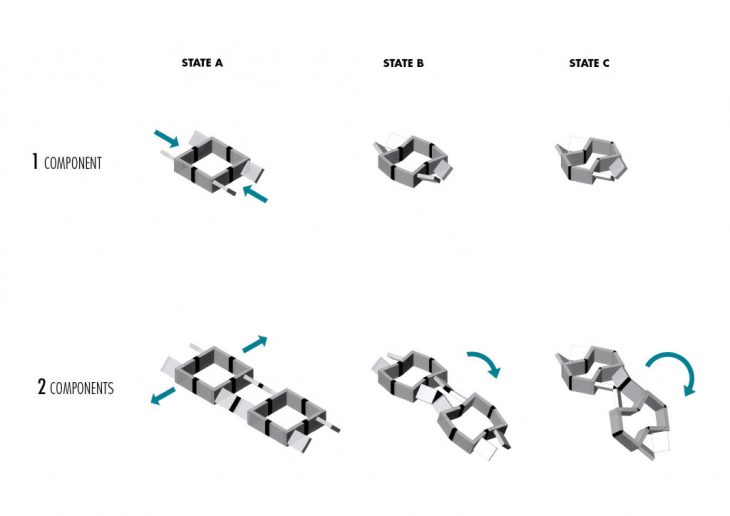
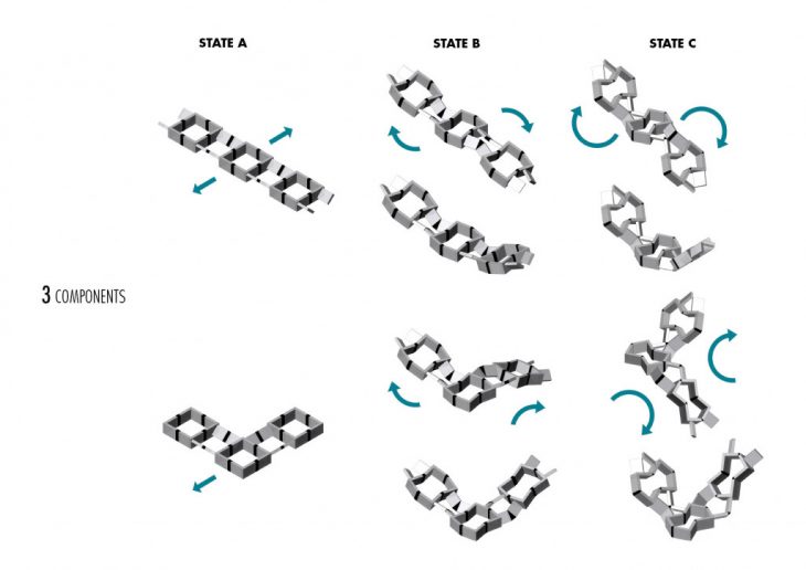
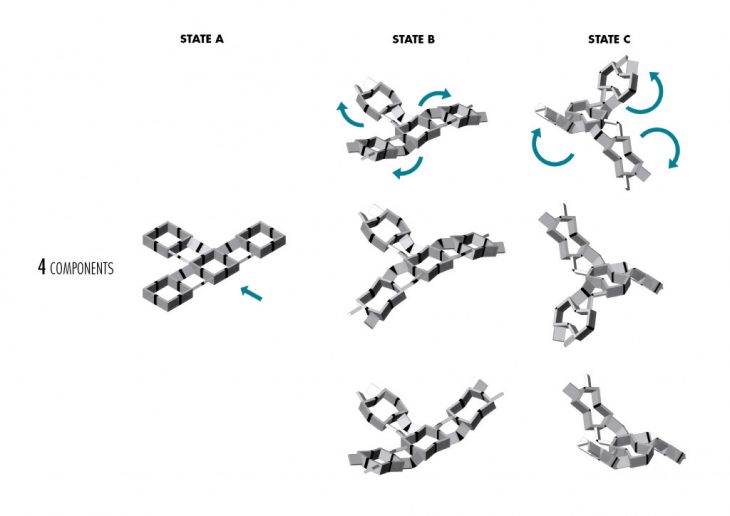
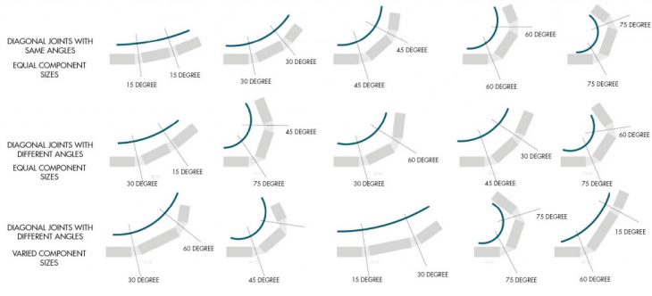
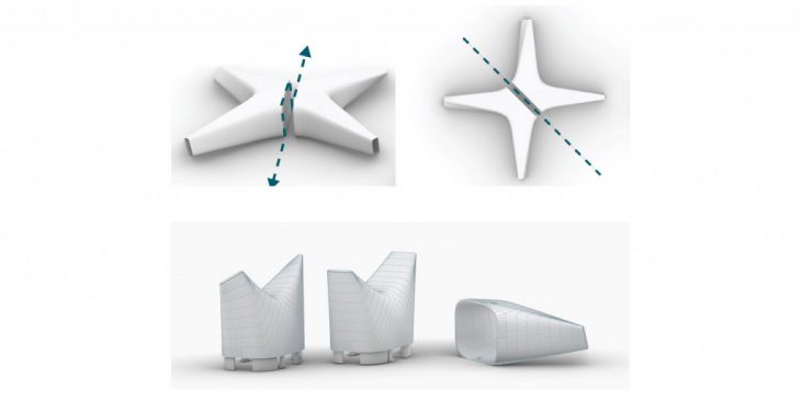
The system consists of multiple components placed in juxtaposition. Each component consists of four axes of rotation. Each axis is connected to the corresponding axis of the adjacent component by means of a joint. The joints thus connect two axes having degrees of rotation that are mutually supplementary i.e. the same degree of rotation that is a mirror of the other.
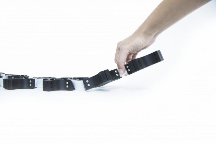
The components connected in a linear fashion, when actuated generates a series of curves of different degrees that depend solely on the rotational angle of the axes. The greater the angle of rotation, the steeper the curve.
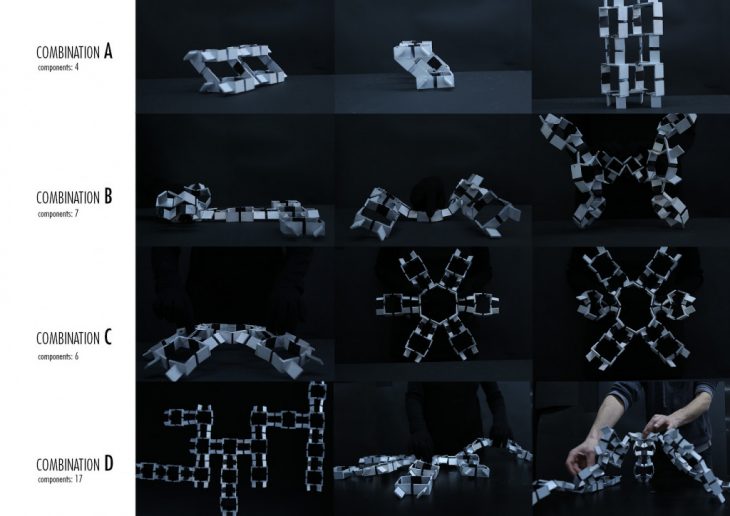
COMPONENT CONFIGURATION CATALOGUE
Uniformed material options were explored in which instead of utilising flexible joints, the thickness of the material itself is manipulated in order to allow for the deformation to occur.
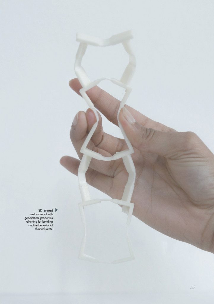
The rotation angle in the component joint defines the degree of bending upon actuation. This property allows for combinations of elements with varying responses to the application of force and therefore the formation of complex configurations
COMPONENT EVOLUTION
Breaking down the design of the referenced component, a limitation in the connection between elements can be observed. Each module provides with two strictly vertical connections and two angled ones. This results in a system in which four components essentially act as one module and it is the connection between those which defines the final geometry. By redesigning the component it is possible to include angled connections in all directions, therefore expanding the potential for complexity and range of geometries which can be achieved. Additionally, the fabrication and assembly time -and effort-, are significantly decreased. The newly created component is a solid piece, as opposed to the referenced which requires multiple attachments to be formed. As a result the new system includes notably fewer connections, therefore vulnerable points, leading to a stiffer, more stable structure.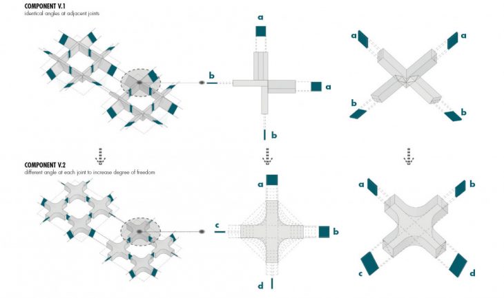
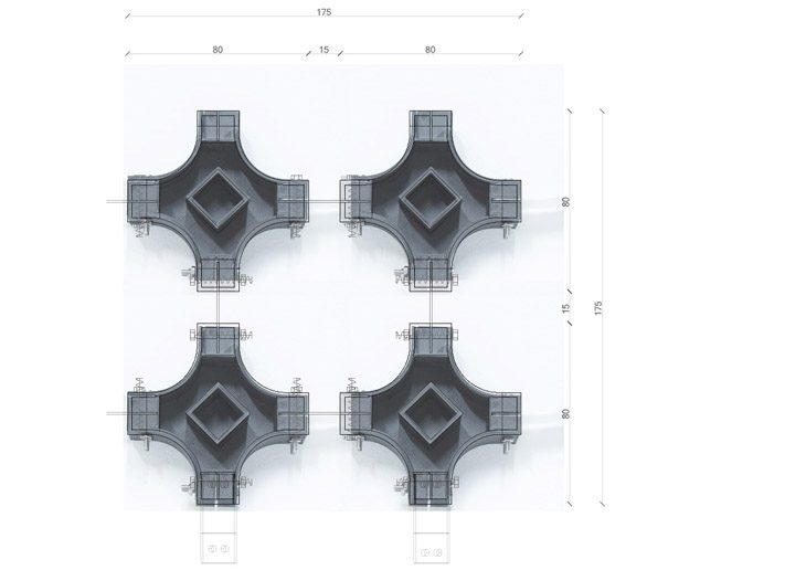
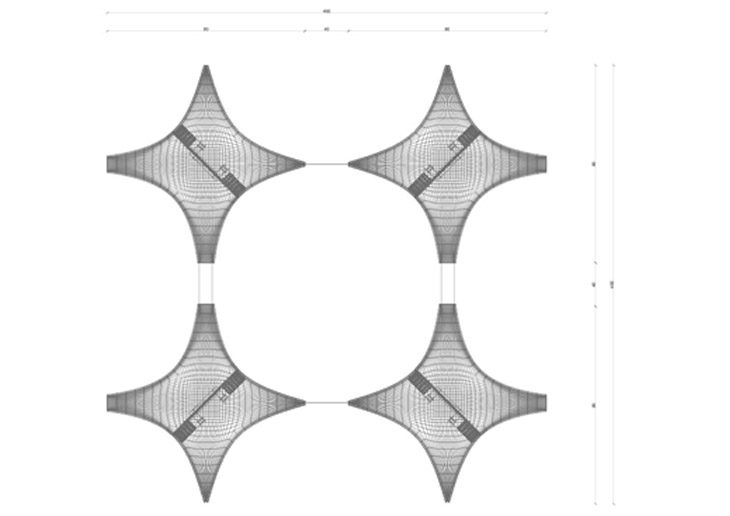
The form of the component is shaped around the axes of rotation. During the process of scaling up, in order to keep the points of intersection between the joints intact, the component assumes the shape of a cross that is rounded or chamfered where the two adjacent members cross paths. The material chosen for the component should essentially be lightweight yet structurally stiff. The material for the joints should be one that is flexible unidirectionally and can resist shear from the perpendicular direction. The distance between each component solely depends on the ability of the joint to distribute the actuation efficiently.
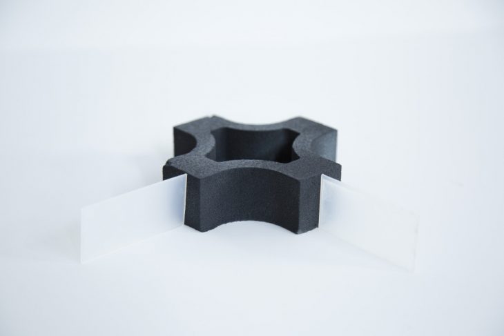
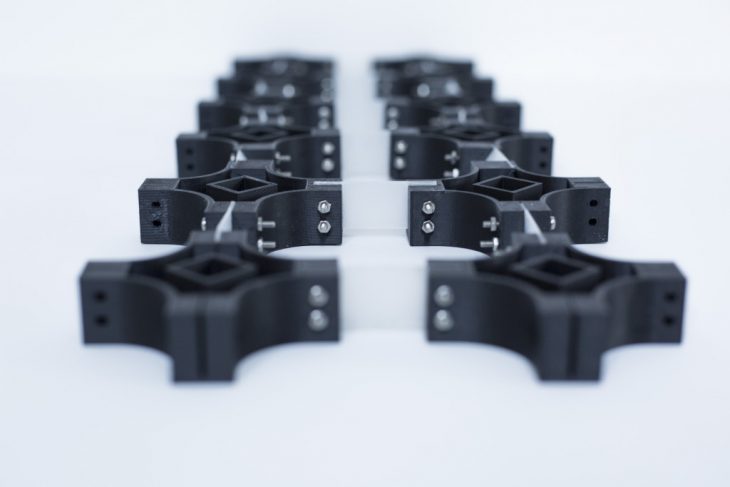
COMPONENT FABRICATION
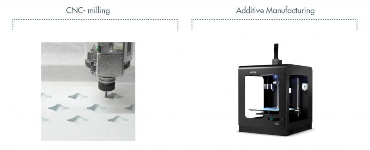
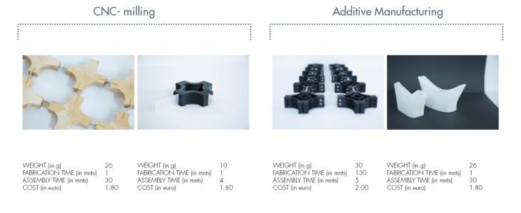
The development of the component involved both additive and subtractive manufacturing processes. While the additive manufacturing (3d printing in this case) proved to be more efficient in terms of precision and detail, the time taken to produce one component is 120 times longer than its equivalent in subtractive manufacturing (CNC milling in this case). The latter however requires post production processes such as sanding and the slitting of the component faces to attach the joints.
FABRICATION R&D
MACHINES USED FOR MASS PRODUCTION AND CUSTOMIZATION
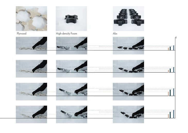
Comparison of the degree of curvature between linear grids of same components produced with 3 different Materials: The plywood components show clear limitation in movement propagation, whereas the 3d printed grid has the most stable form of connection.
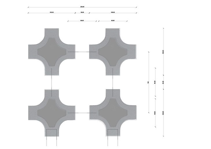
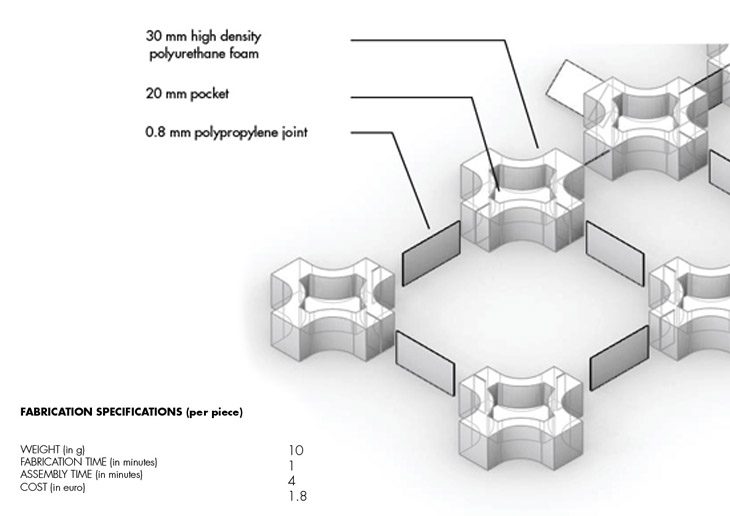
The component made out of foam is milled by a 3 axis CNC machine from high density polyurethane foam. In order to make the component lighter by weight so as to increase efficiency of propagation, each component is pocketed in the centre. The amount of pocketing depends on the structural duress incident on each individual component while still maintaining the integrity of its form. The joints for these foam components are of polypropylene that is laser cut to the appropriate size. The total length of the joint is 50 mm, 15mm of which on either side are wedged and glued inside the neighbouring components hence making the length of the joint between each component 30mm. Incisions of the correct rotational angle are made onto the components by means of a metal blade, guided by a 3D printed cap that fits onto the face of each component.
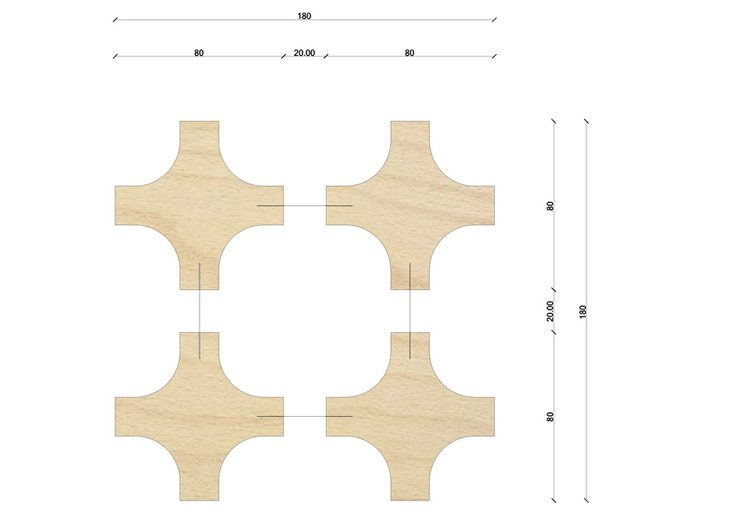
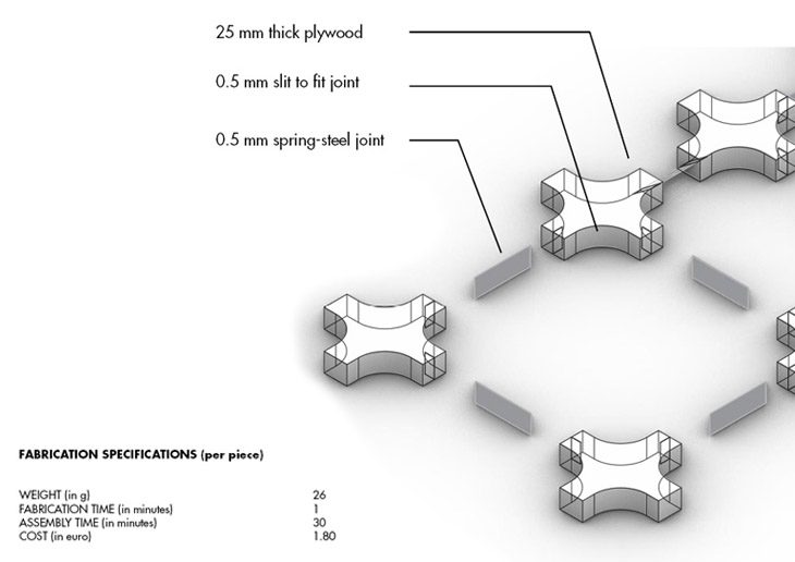
The second attempt at prototyping was done from milling plywood with the joints connecting them comprising of springsteel. This prototype presented more challenges due to the rigidity of the spring steel and the lack of distance between the components so as to provide ample radius of bending for the springsteel to avoid plastic deformation.
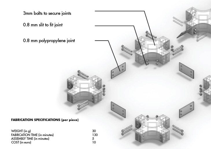
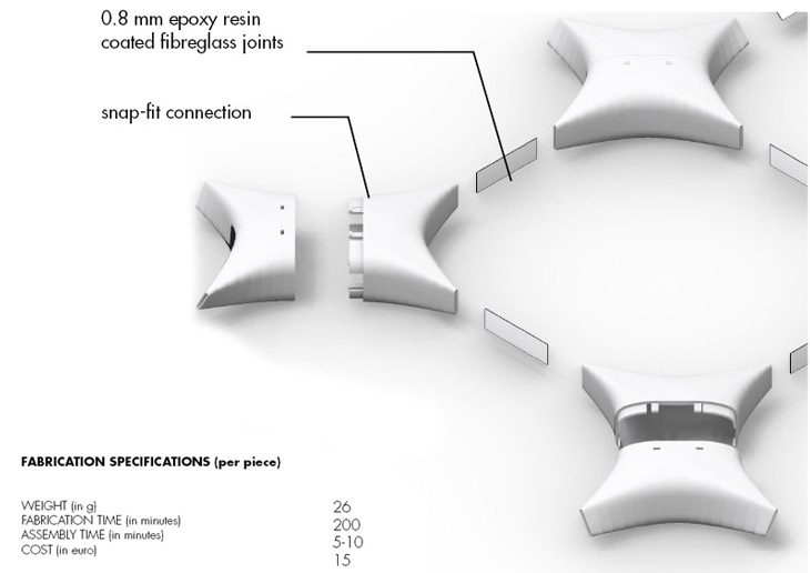
The additive manufacturing process consists of 3d printing the component. This method offers a greater degree of precision as the components can come prepared with the slits already in place along with provisions for the joint to be bolted securely in place to the component thus increasing the efficiency of propagation.Assembly time per component is relatively short at 4 minutes but the time to produce a single component is about 130 minutes which is 120 times the amount of time to produce the corresponding high density foam component. The joints are of 0.8mm polypropylene and the length of the joint here is 30mm between the components.
SURFACE PRODUCTION
THE GRID
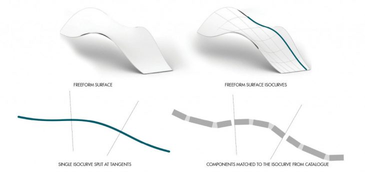
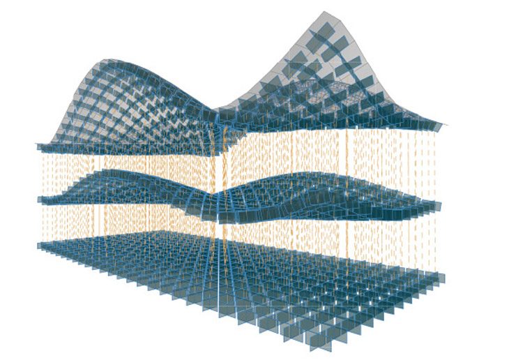
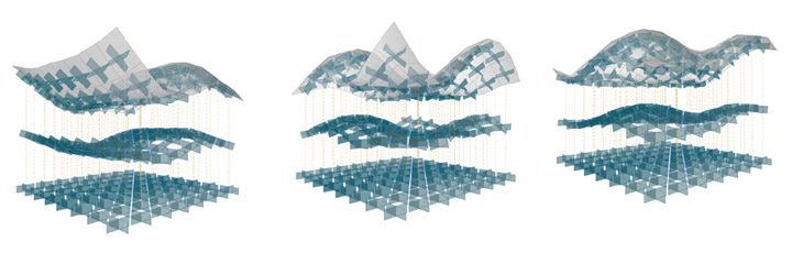
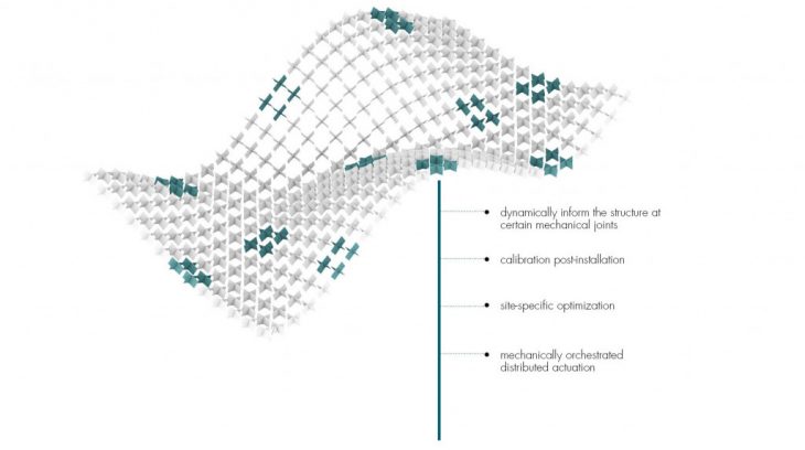
The components when placed in a grid as a series of interconnected linear spines, give rise to a freeform surface at actuation. Depending on the angles that have been preprogrammed into the components, different freeform surfaces can be produced assuming that the joints propagate with 100% efficiency. Specific points on the grid are the main actuation points and these depend on the geometry of the freeform surface surface such as the tangential points, the points of structural integrity as well as the position of support of the surface.
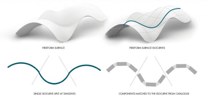
By altering the rotational connecting angle and the component size it is possible to approximate a wide range of curves. In a similar manner, isocurves, or spines, of complex freeform surfaces can be replicated. The replication of the network of isocurves will result in the desired target surface.
COMPUTATIONAL APPROACH
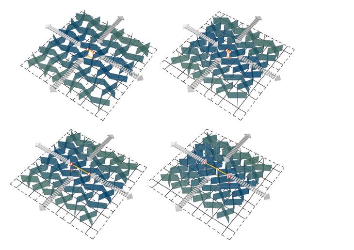
Simulating the auxetic behaviour
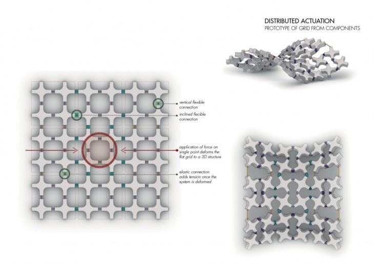
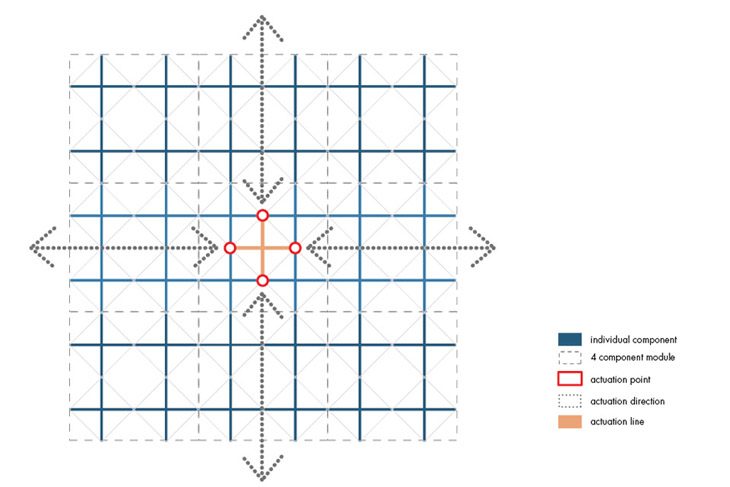
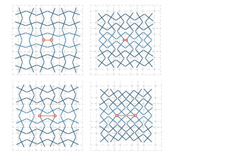
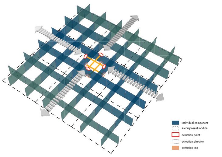
The components placed in a grid when actuated, display properties similar to the auxetic honeycomb in order to propagate or distribute the actuation. The point of actuation occurs between a set of four components and is bidirectional. Based on the way the component is actuated (in either direction), the inherent auxetic property flips the curve translated by the components in the opposite direction to attain a stable actuated state.
Projecting the component on freeform surfaces
SURFACE GENERATION
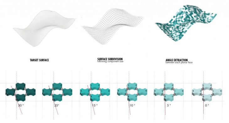
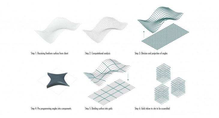
Surface generation to identify number of grids and angles between components
Computationally, the surface is divided according to the size of the component after which each component from a flat state is mapped onto the surface in its projected form. This along with calculating the angles between the normals of each component on the surface gives rise to the necessary angles that the component must have in order to acquire the right form.
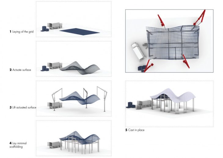
FLEXIBLE DYNAMIC FORMWORK

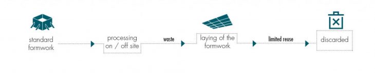
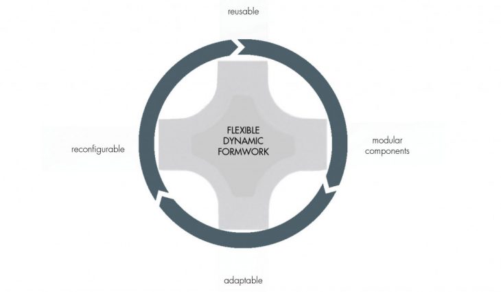
Flexible formwork as a sustainable cycle in re-purposing formworks used in construction with an aim to reduce construction waste which takes up to 30 % of total waste in certain cities in Europe
There is an increasing need to produce an architecture that can keep pace with the diverse possibilities that digital designs provide and bridge the gap between ideal optimised conditions and what can be actually physically realised materially.
Advancements in the computational realm opt for bespoke designs. A dynamic, responsive architecture is the solution to a sustainable, long term system that can provide for such customised operations.
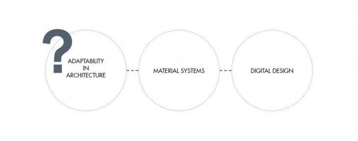
Adaptability in architecture is achieved through a hybrid of material systems research and digital design. In this research, a response to adaptability is studied in two paths: flexible dynamic formworks as a construction solution for freeform surfaces, and reconfigurable responsive structures that are pre-programmed and have a shape shifting ability post-construction.
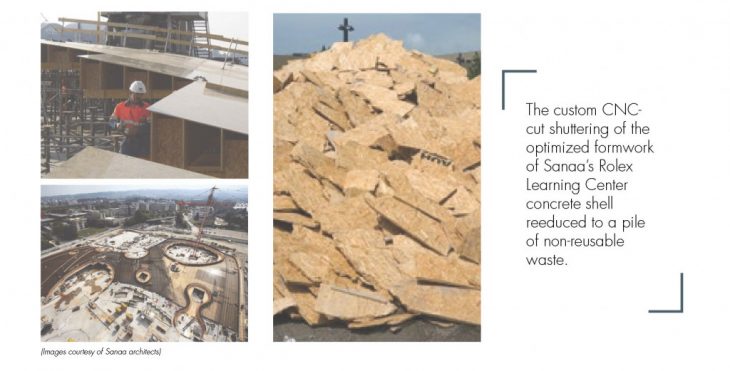
EXISTING RESEARCH IN THE FIELD OF FLEXIBLE FORMWORKS
SURFACE MOLDING
EXPLORATION OF MOLDING A SURFACE ON THE ACTUATED FORMWORK
COMPONENT OPTIMIZED DESIGN
Diagonal slit on new component to cater for a variety of angles and facilitate the fabrication process.
The optimized final component is designed so as to accommodate a smooth transition between the joints of the adjacent components and to provide an ideal surface on which a fabric can be stretched upon for molding material on the ensuing formwork. In the component grid system, in order to obtain different curve configurations, the optimised component is designed in halves which snap-fit with each other. These halves can then be exchanged with other component halves so as to get a variety of curves and also to facilitate ease of transportation by stacking.
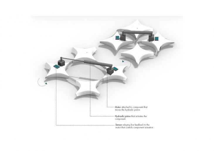
A hydraulic motorized system embedded on the components allows for the calibration of the formwork after local actuation in order to precisely match the desired target surface
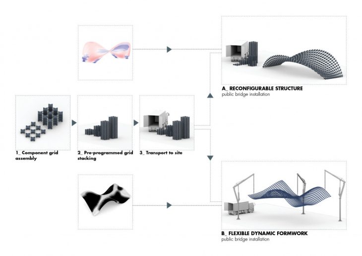
DESIGN TO FABRICATION CYCLE
INSTALLATION STRATEGY
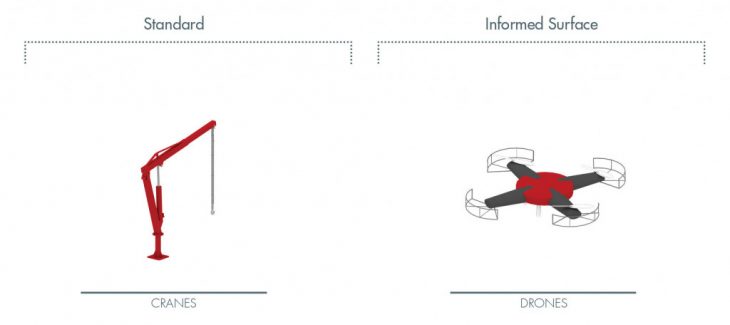
Methods used to lift the freeform surface can vary according to the level of customization and information attributed to the surface, as well as cost implication.
Looking into both scenarios of the system as a responsive reconfigurable structure and an adaptive formwork, the strategies for utilizitation of the system starting with off site production, packing and shipping, to on site assembly, actuation and placement are explained below.
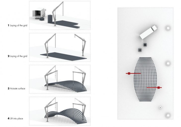
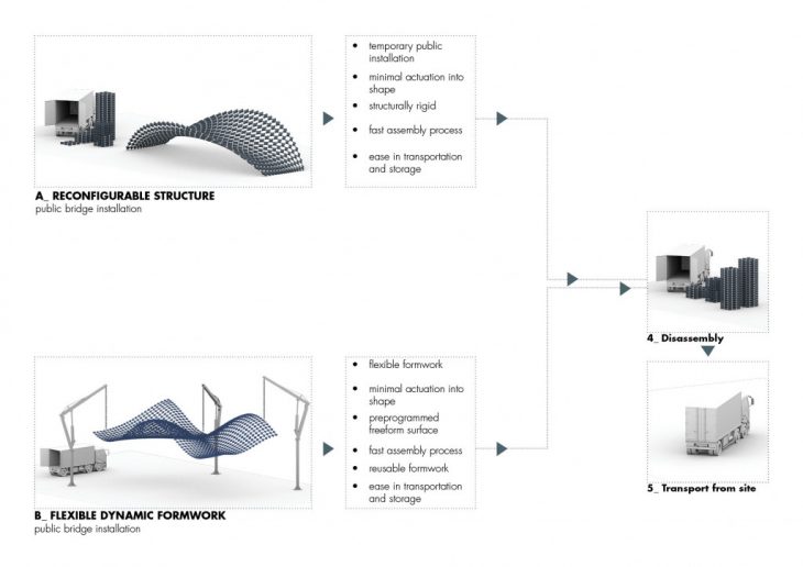
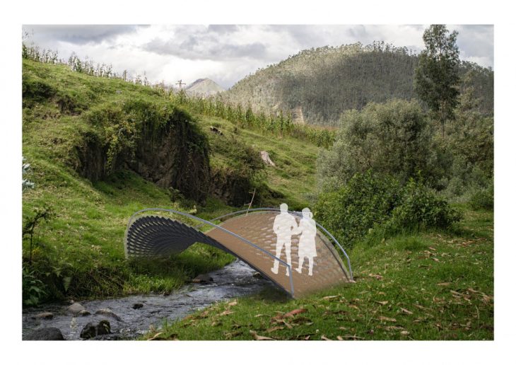
Visualisation of the system as a deployable bridge
OTHER APPLICATIONS
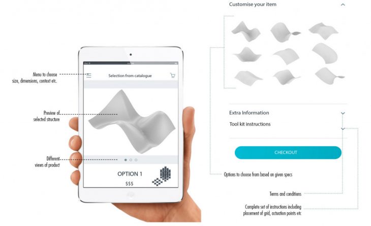
METAFORM AS AN ACCESSIBLE KIT
ESTABLISHMENT OF A USER INTERFACE TO PROVIDE RECONFIGURABLE
SURFACES AS A PRODUCT BUILDING KIT
OUTLOOK
METAFORM can be used in various applications from temporary kinetic structures to shape changing formwork for lightweight fiber structures. The process of scalability is tackled by insuring the structural stability of the actuated surface which can only be achieved by the use of a rigid lightweight material at component scale. Modifying the density of a grid of components allows for the configuration of a large spectrum of freeform surfaces obtained from a flat grid, with a restrained number of manual and or mechanical actuation, locally distributed along the grid.
METAFORM suggests a sustainable alternative solution to adaptability in architecture, offering an outlook on how we design and fabricate freeform surfaces.
METAFORM is a project of IAAC, Institute for Advanced Architecture of Catalonia developed at Masters in Advanced Architecture in 2019 by:
Students: Ankita Alessandra Bob, Antonis Nikitaras, Yara Tayoun
Faculty: Areti Markopoulou, David Andres Leon, Raimund Krenmüller Student Assistant: Nikol Kirova