Modular Aggregations and Structures is a project of IaaC, Institute for Advanced Architecture of Catalonia
developed at Master in Advanced Computation for Architecture & Design in (2020/2021) by:
Students: Krishnanunni Vijayakumar, Keshava Narayan and Aleksander Mastalski
Faculties: Manja Van de Worp
Analyzing and exploring staggered floor structural systems and integrating the results into a modular aggregated structure.
STAGGERED FLOOR SYSTEMS
Staggered floor system is a structural system with floors broken down into various levels increasing the number of connections vertically within the structure. A typical example of such a system is the N A House by Sou Fujimoto.
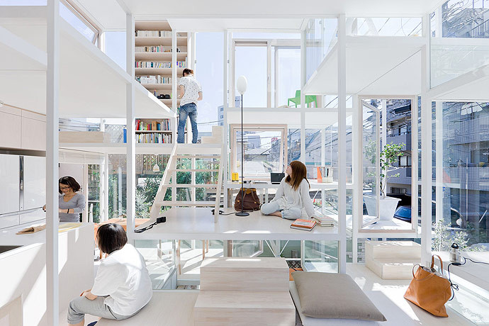
Source : sou-fujimoto.net
Ranging in size from 21 to 81 square-feet, each floor plate is linked by a variety of stairs and ladders, including short runs of fixed and movable steps. Stratifying floor plates in a furniture-like scale allows the structure to serve many types of functions, such as providing for circulation, seating and workings spaces. The short-spans allow for the thinness of the white steel frame.
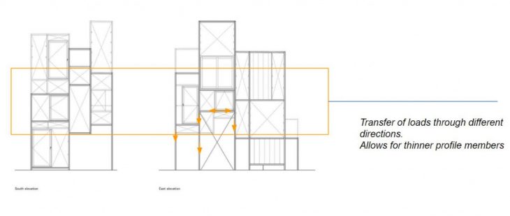
The structure is made of thin profiles with joints at various levels.
The redundancy of joints make structure more stable. Thinner profiles can be used as the structure is more rigid, loads are transferred to various members.
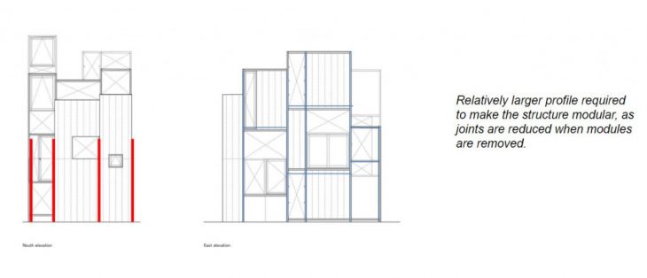
Modularity is possible in such a system if modules below are Efficient enough to support the ones above individually.
DESIGN OF ANALYSIS MODEL

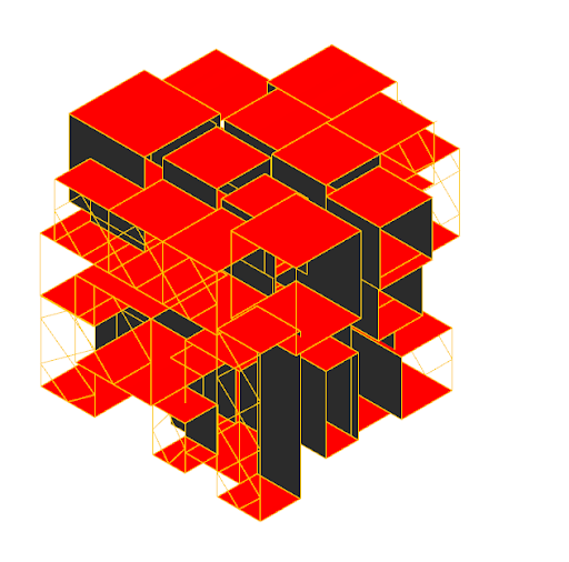
The geometry is derived by generating parameterized volumes which are multiples of 0.5m. The volumes are then clustered using physical engine by specifying center of gravity and proceeding physical collisions between each other until reaching equilibrium state.
Different iterations can be achieved by changing the original volumes and running simulation again.
Presented boxes are based on randomized values, as design progresses we are aiming for analysis based parameters.
2D SECTION ANALYSIS
Variations of 2d section is analyzed and compared to find out the change in structural behavior based on material. The first section considered has diagonal bracings for added supports. The second option introduces a central concrete column and the third option has the central columns cantilevering into the timber grids.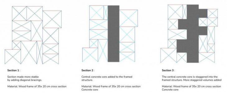
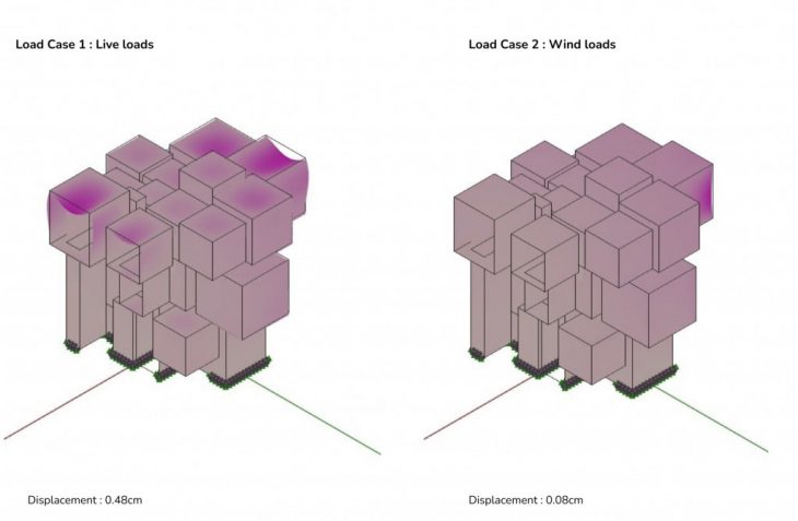
DISPLACEMENT
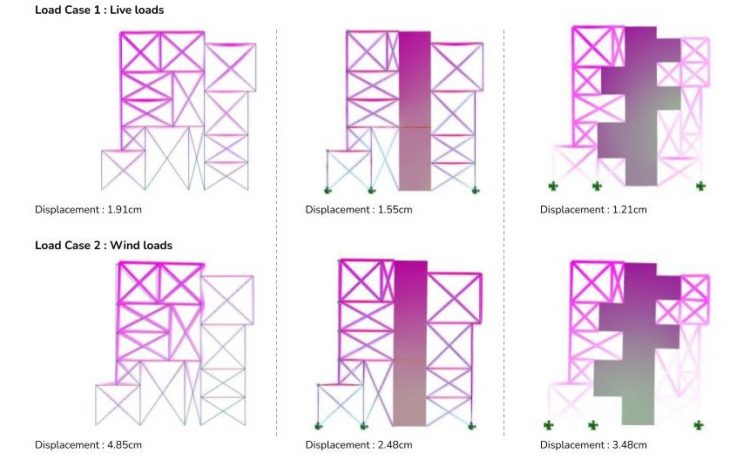
Section 1: Displacement is maximum towards the top of the structure for both load cases. Displacement in case of wind load is concentrated on the volumes in direction of the wind load.
Section 2: Displacement is more uniform throughout the structure with lesser displacement towards the supports.
Section 3: Displacement on the core is more towards the support.
From this analysis, we concluded that the displacements are less for section 2 and 3 as compared to that of the option with only timber frames. Additional cantilevering of central core has a negative impact adding more displacement and instability.
3D ANALYSIS
The 3D analysis of the system aims in understanding the differences in structural performance based on the orientation and positioning of walls. All walls are considered as cot walls 10cm thick.For the first option all walls are considered as closed, at maximum enclosure. This is then analysed with gravity, wind and self load acting on it.
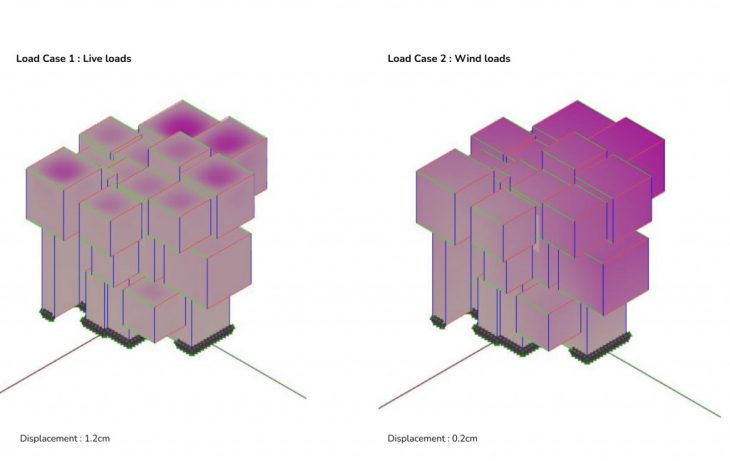
Centre of the floor slabs experience maximum displacement. This shows that the thickness of the slab has to be increased. Relatively lesser deflection is experienced with wind load, and is lowest for the blocks with highest neighbouring connections.
For the next variation, walls along y direction is removed to improve maximum view and movement towards this direction. Displacement was found to be higher for cantilevers with wall removed from the sides as opposed to the ones with walls removed from the cantilevering edge.
The third variation had concrete shear walls added at the centre to act as a split core. Based on previous analysis the cantilevering units have walls removed at the edge that is cantilevering out.
Overall displacement is reduced for both load cases. Greater displacement on slabs are the cantaloupe ring edge. But is relatively very low compared to the previous option.
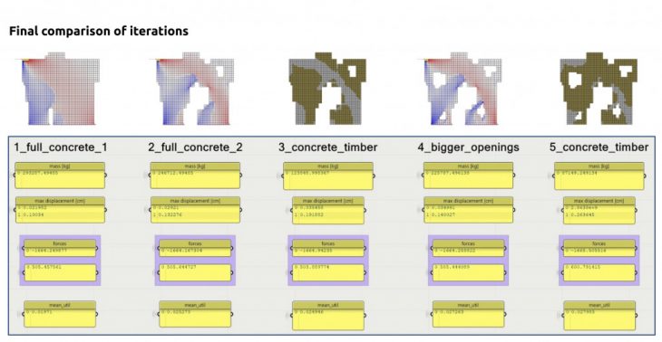
WALL ANALYSIS
The next exercise involved creating a wall, and then analysing this wall to extract the stress lines and then understanding where openings can be provided. For this an initial wall was created by combining all walls into one .
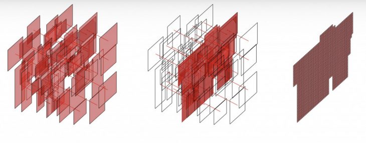
All faces are stacked on top of each other and using algorithm, this is converted into 0.5 x 0.5m meshes. The duplicates are culled and the geometry is made ready for Karamba analysis.
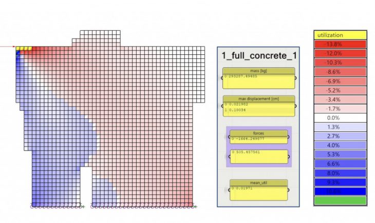
Stacked mass is then analysed. The shell was kept as concrete. Based on the utilisation analysis openings where introduced into the wall at areas of no utilisation. Further analysis was done on this model to extract force flow as well as stress lines.
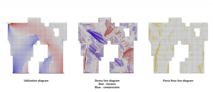
A mix of concrete and Tiber system was introduced. This reduced the overall building mass. Mean utilisation is reduced from 2.52 to 2.48. The diagram below shows a comparative analysis of the various iterations.
MODULAR EDIFICE : Structural Analysis
WHY MODULAR?
Modular entities have objects which repeat with respect to each other. eg. Cells Modularity can also lead to sustainability as the formwork used to build one module can be repeated to build the other modules hence saving material, money, as well as time. Modularity can allow for phase wise construction which can help in incremental building
SITE
The site is located in a bustling industrial area next to a comparatively idle port in the city of Mumbai. The urban fabric consists of majorly commercial buildings and warehouses as this is an industrial area. The site is closer to the east coast of the Mumbai City.
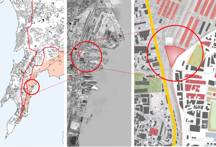
The site is accessible through road and rail and within 5 minutes of walk from the nearest railway station (Reay Road) and it is located on two main roads. Hence the site is a potential commercial center lying undeveloped because of the heavy noise from the surroundings.
Plot size : 300 x 200 m
PROGRAM
The proposed programs for the site are a public retail area with landscaped paths at the site level and a commercial office space for the rest of the building.

The programmatic requirements for a co-working space in general are studied in order to be incorporated in the proposal. Public spaces like the library, cafeteria.
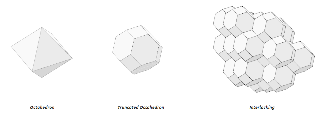
Developing interlocking modular approach:
The modules were redeveloped according to the learnings to prepare the final versions for aggregation.
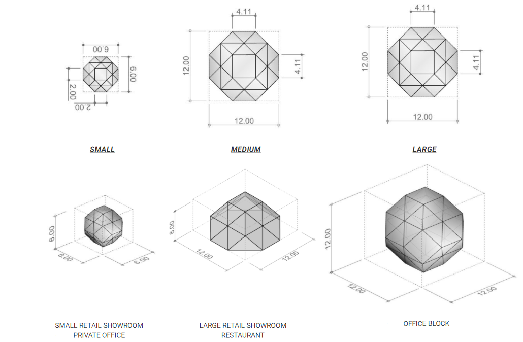
Proposed solutions for function in single modules and clusters
The shared pods can be attached to the larger modules which can be a cabin for a single person as well as for 2 people as shown.

A small composition of the modules showing the different functions.

OVERALL FORM FINDING
FORM FINDING USING WALLACEI OPTIMIZATION

FV1, FV2 Maximum exposure towards ocean (East) and South
FV3 Minimum exposure towards West (sun radiation and view improvement)
FV4 Minimum total sun radiation (yearly analysis)
FV5 Aim for volume range of: 30 000 – 31 000 m3
Chosen iteration that fits both the fitness values and the overall appease.
INTEGRATION OF SIMULATION AND MODULARITY
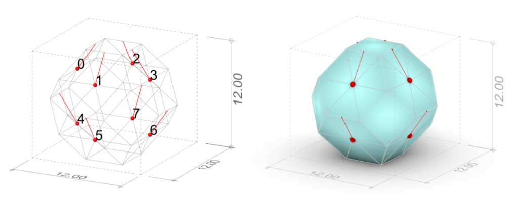
By using Wasp plugin the geometry that was found using simulation was aggregated with truncated octahedron modules. The initial modular approach was tested.
INITIAL 3D ANALYSIS
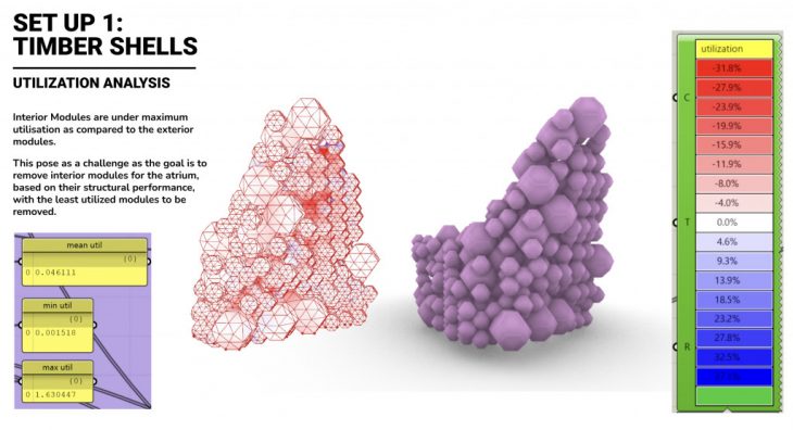
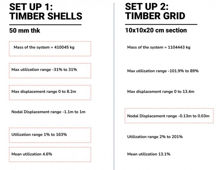
The aggregated modules are considered as two variations for the initial 3D analysis, as a shell model and a beam model.
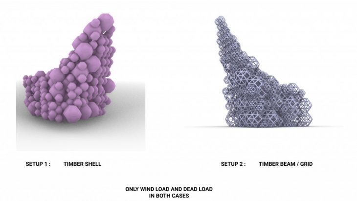
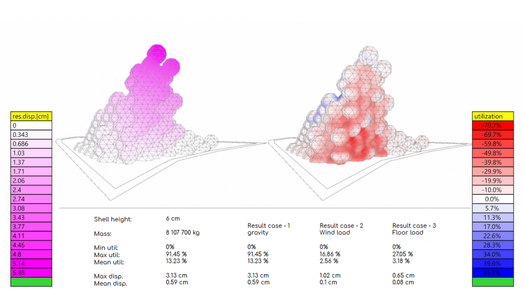
The triangulated structural grids are considered as shells for the overall analysis with a wood shell of 50 cm thick.
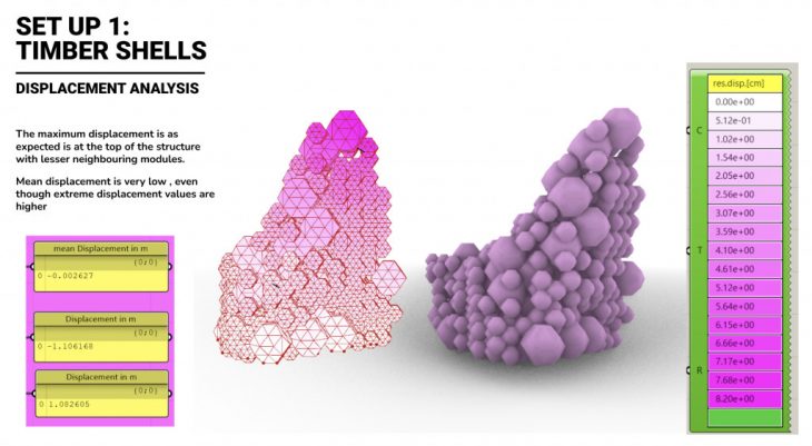
Displacement analysis reveals that the structure is displaced the most at the top , with modules having very less neighbours. Mean displacement values remain very low, even when extreme displacement values are very high.
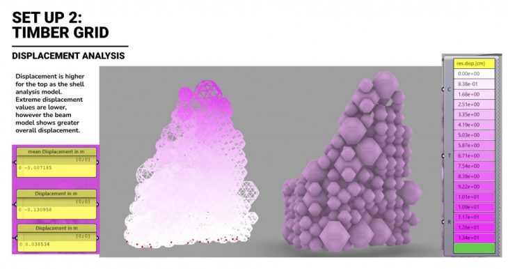
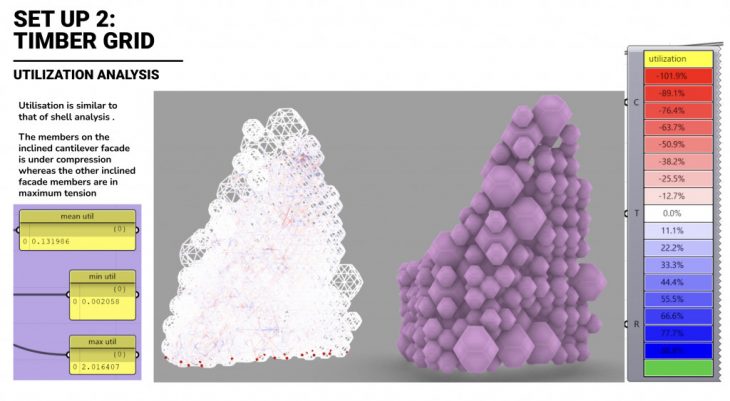
For the second variation all structural members are considered as interconnected octahedron network of beams. Displacement was found to be higher for the top of the structure here as well, with simple behaviour as that of the shell model. However the beam model showed greater overall displacement.
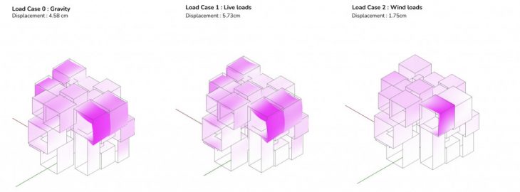
FINAL STRUCTURAL ANALYSIS
The final form chosen was structurally analyzed to understand the benefits and shortcomings of the form which can help in programmatic distribution.

The simulation model was prepared and analyzed based on the following result cases:
- Gravity
- Wind load analyzed for 2 predominant directions
a. West – facade area 4226 m2
b. North – facade area 3505 m2
Force: 1.5 kN/m2 - Floor load
Total area: 12 928m2 Force: 1.5 kN/m2
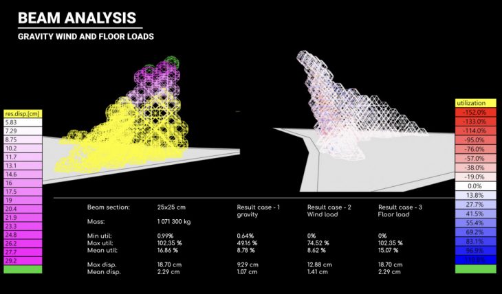
The model was analyzed using two approaches. The first one was the shell model (h=6cm), the second was a rectangular timber beam model (24 x 24cm). Final iteration was further reinforced by introducing steel grid(8 x 8cm) in atrium to improve overall performance and decrease total mass of the building.
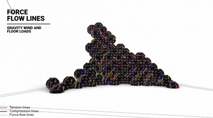
The force flow lines are extracted from the model with compressive and tensile forces.
The beam model is then analysed and there is a slight increase in the displacement values. The extreme displacement values have increased drastically whereas the mean values remains at a similar scale. There is also a significant reduction in the total mass used. Thus a beam model was considered for further analysis.
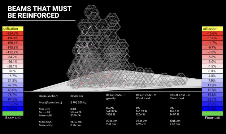
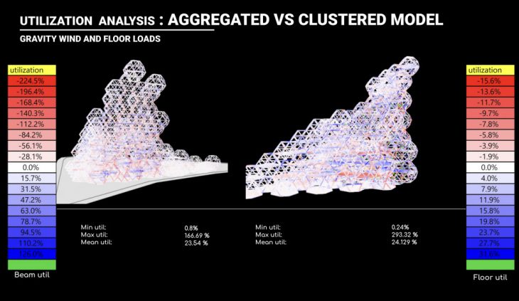
From the beam model utilisation analysis a grasshopper script is used to isolate the members that are almost fully utilised. The modules containing these members are considered as structurally significant and is hence not considered for the clustering process that is to follow.
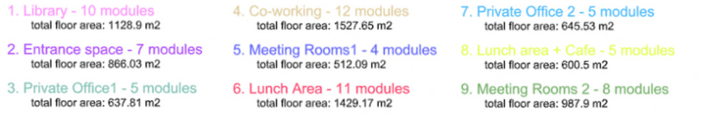
PROGRAM CLUSTERING
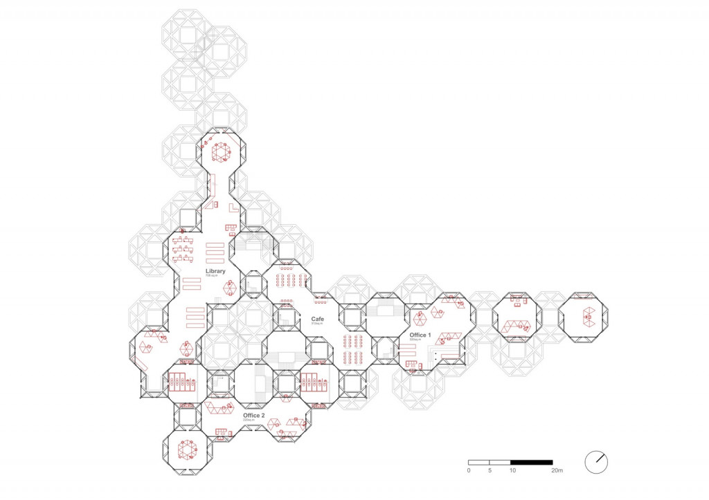
Based on earlier analysis and module clustering algorithm the function was distributed into the aggregation.
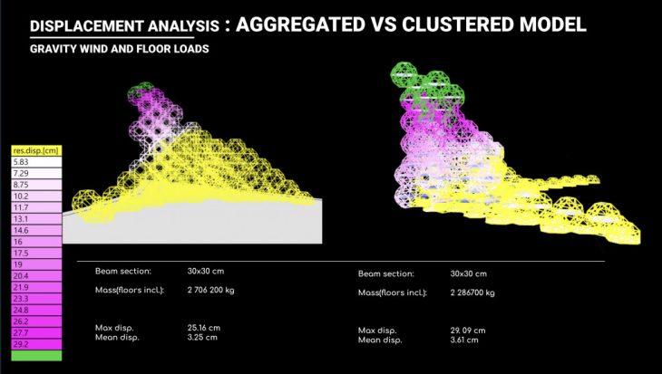
This clustered model is then structurally analysed and compared to the previous version. As expected the maximum and minimum displacement values climb up. But the mean values remain similar. Also there is a 15% reduction in the overall mass.
The bending moments and axial forces are extracted. The bending moment diagram showed that the introduction of atrium has made the building to perform as two parts with the part containing the inclined facade showing maximum bending.
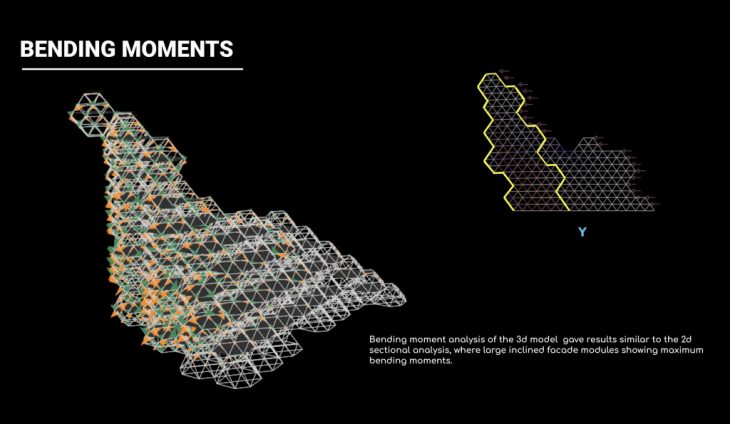
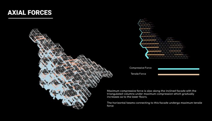
A similar observation was seen for the force flow as well with maximum compressive forces on the inclined facade.
The inference made from this was the vacant atrium is creating a very noticeable difference in structural behaviour of the entire system. So the final step was to introduce thinner steel grids of the same octahedron network into the atrium, connecting the whole structure together.
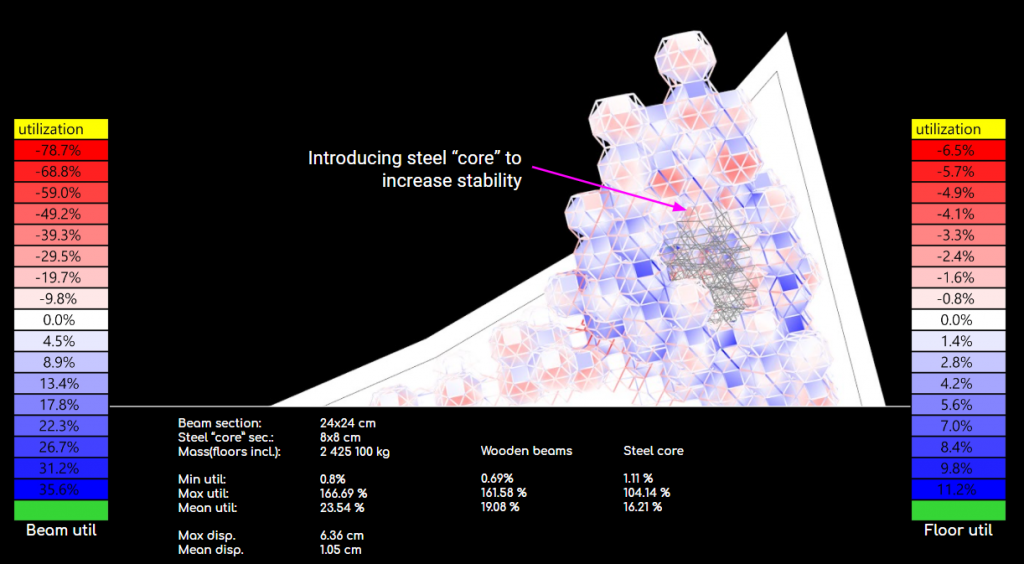
The addition of the steel grid showed positive results. The maximum and mean displacement which were very high has now reduced drastically. The mean displacement has also reduced considerably. These steel grids are then used to form the circulation paths through the building.
Main circulation inside the building was designed to be located in the atrium. [white modules are communication]

Exemplary floor plan.
Exemplary sections.
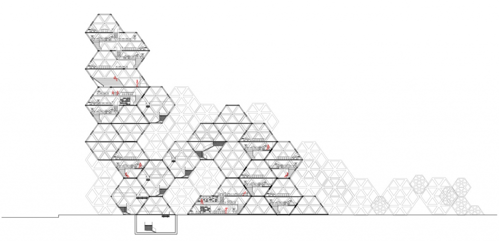
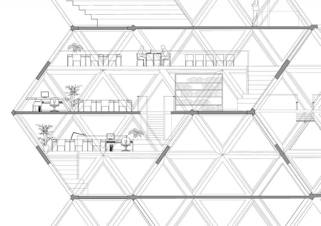
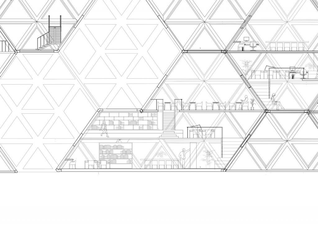
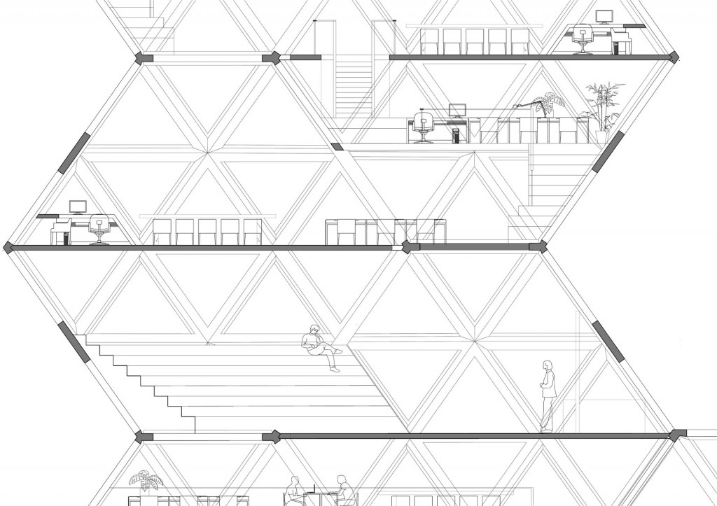
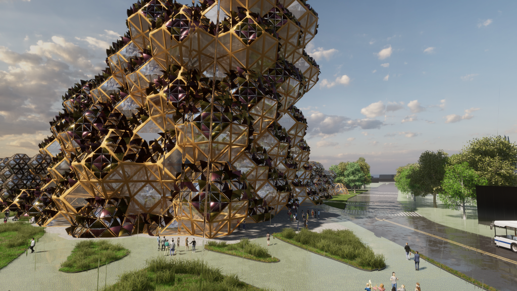
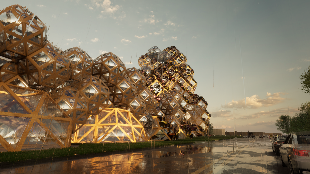
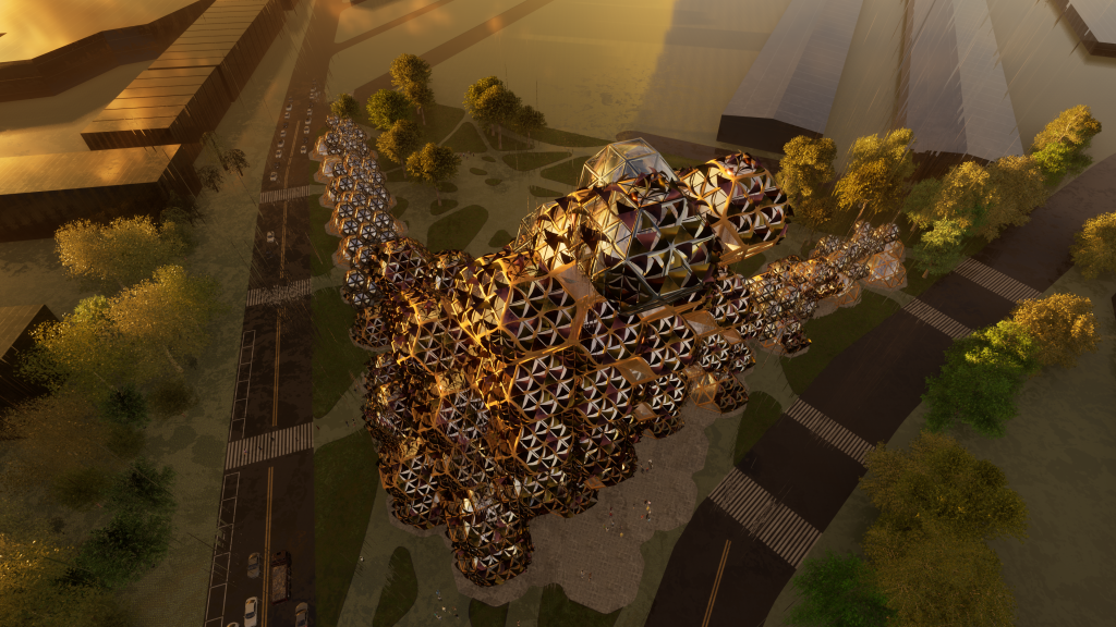
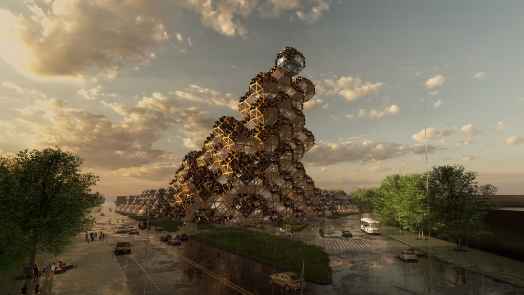
FINAL RENDERS