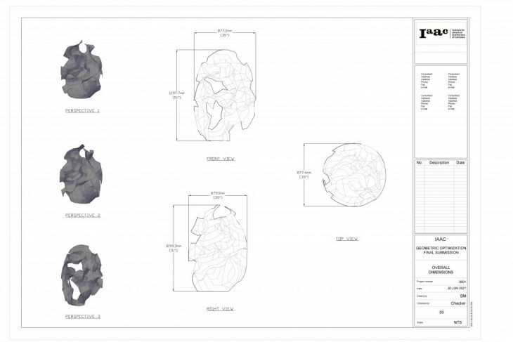
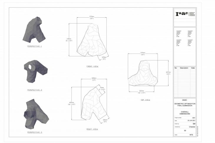
GEOMETRICAL OPTIMIZATION
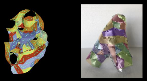
The objective of the Geometrical Optimization project was to find the shortest path using triangulated mesh faces of a complex geometry, limited by the maximum number of faces, in order to fabricate using flat materials such as aluminum. The project went through multiple iterations where different types of forms with varying complexities were rationalized, made using paper models, compared, and then prototypes in aluminum. Ultimately the project drew conclusions based on lessons learned with respect to the stripping technique, fabrication technique, materials used, design of the fastening tabs, and the complexity in curvatures of the forms.
Our initial form finding was based on the minimal surface typology inspired by Eva Hild sculpture as well as the sculptures done by THEVERYMANY.
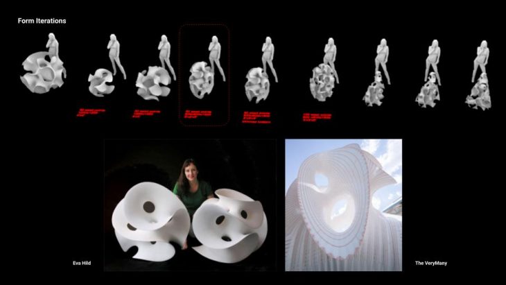
Form Finding and Initial Inspiration
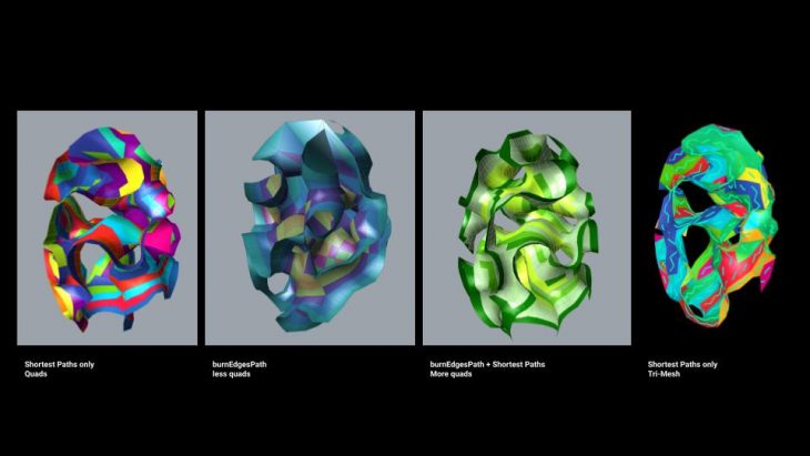
A variety of iterations on rationalization techniques were tested to achieve strips adequate for fabrication. Both quad and tri meshing was explored. Shortest path and burn edges and the combination of both algorithms were used to explore rationalization options. The following observations have been made:
- Burn edges algorithm for quad-mesh resulted in the least number of strips, however they were very long. The strip after unrolling was often clashing with itself multiple times and required splitting at specific locations to avoid that
- Burn edges algorithm used for few iterations combined with shortest path for the rest of the mesh provided visually appealing configuration as well as less amount of strips
- the attempts to planarize the original quad-mesh resulted in a form that did not resemble the original shape
- Burn edges algorithm did not provide satisfactory results while using tri-mesh
- Shortest path algorithm used with tri-mesh proved to be most effective workflow for fabrication keeping the desired original complex shape
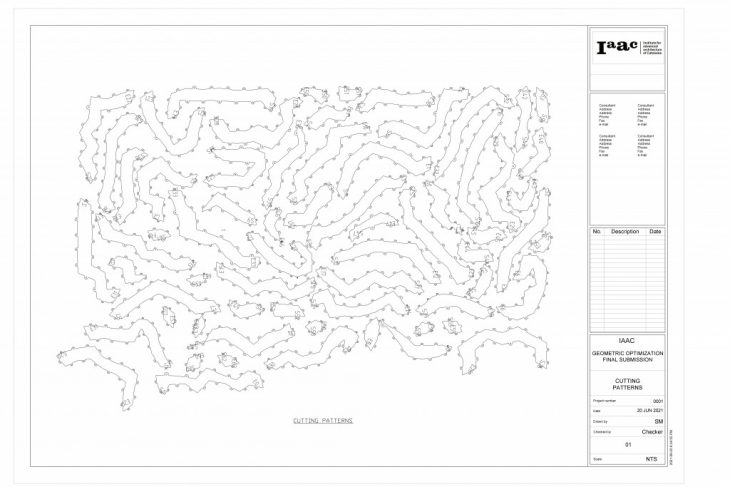
Rationalization trials
Due to the limitations of fabrication, both for paper as well as the aluminum model, the maximum number of faces on the strips was established. The limiting condition was set inside the python code and the maximum number of faces was introduced as an input parameter to the hops component.
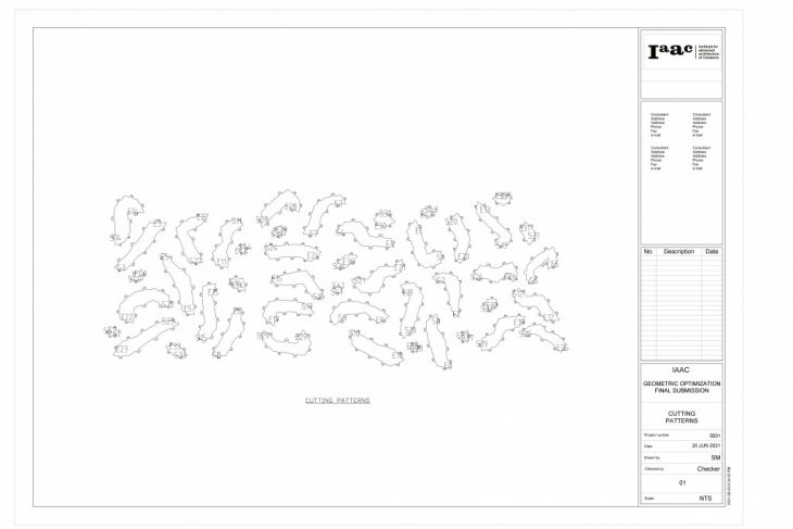
Strip Nesting
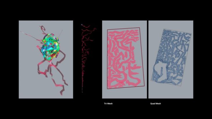
The following video shows our grasshopper workflow. It starts with using hops component in order to connect to python code running on a flask server. The code is responsible for creating a graph out of the input mesh and running algorithms to find suitable paths based on input weights. For the final iteration, the shortest path algorithm using mesh edge length was used.
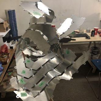
After dividing the mesh into strips, each part can be inspected visually using color previews. Then, text is applied to the start and end face of the strip to help with the fabrication. The strips are unrolled using Open Nest and arranged within boundaries. The same text corresponding to the start and end face of the strip is applied to the 2D nested patterns as well so cross referencing the cut parts to the model can be easy. Finally, the tabs are added to the strips to allow for connection of the strips.
The results of the workflow were shop drawings, 3d patterns and measurements.
Iteration 01 – Shop Drawing 01
Iteration 01 – Shop Drawing 02
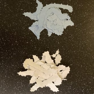
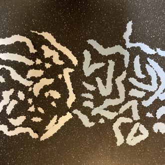
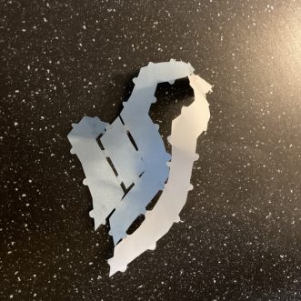
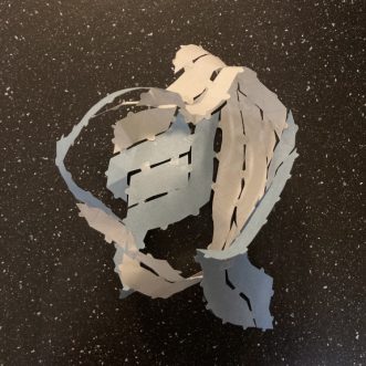
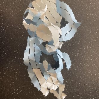
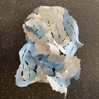
For the initial paper model, fabrication plans consisted of 6 sheets of A4 size. The following images show the step by step process of assembly. The paper model allowed us to identify potential issues in the workflow and possible problems for the future full scale model.
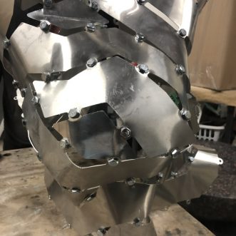
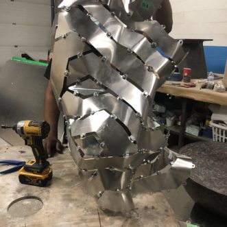
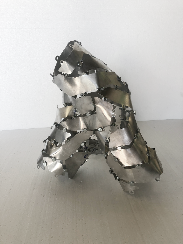
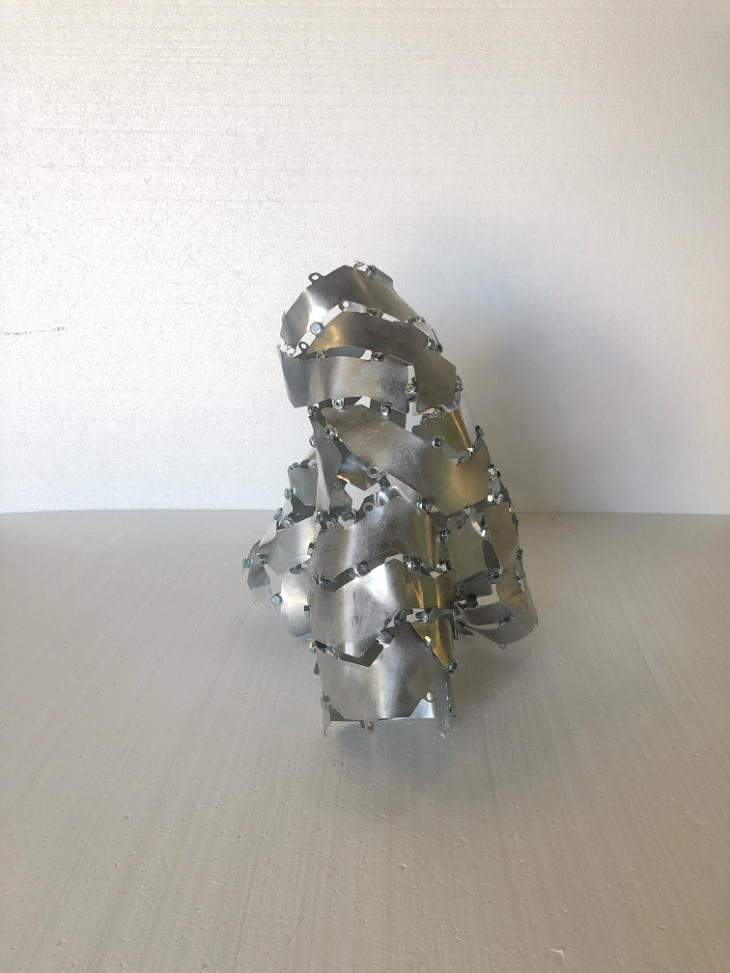
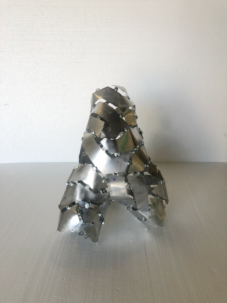
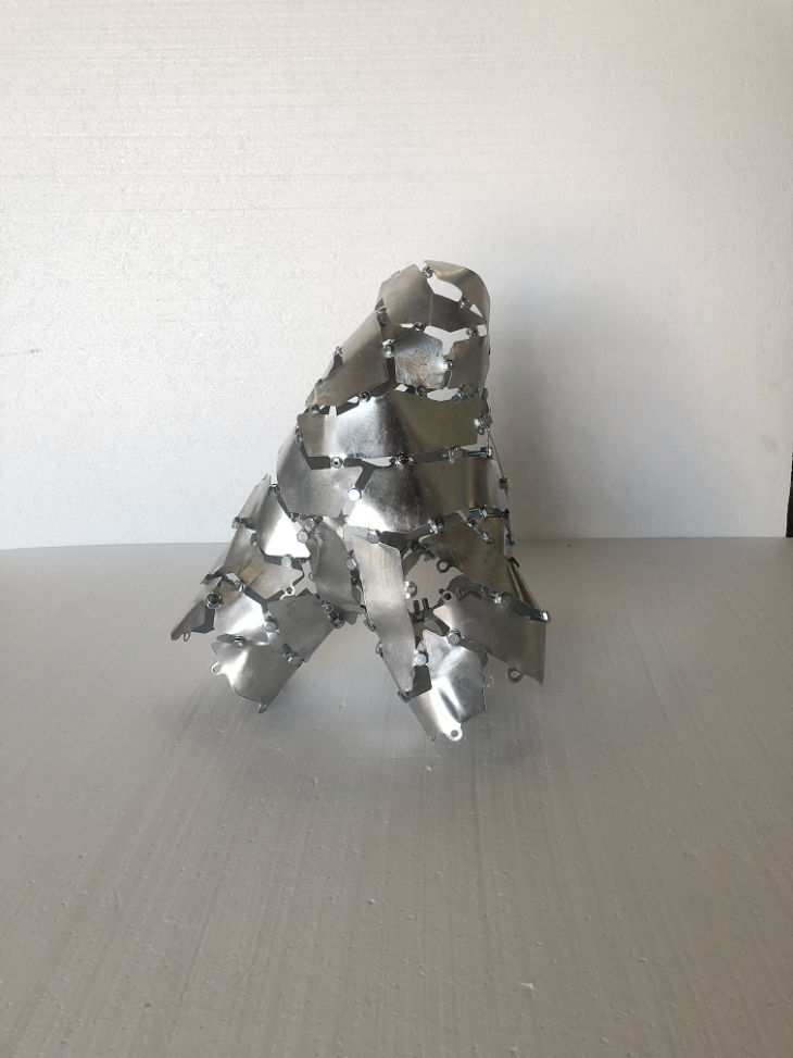
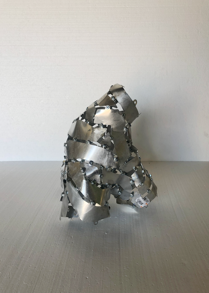
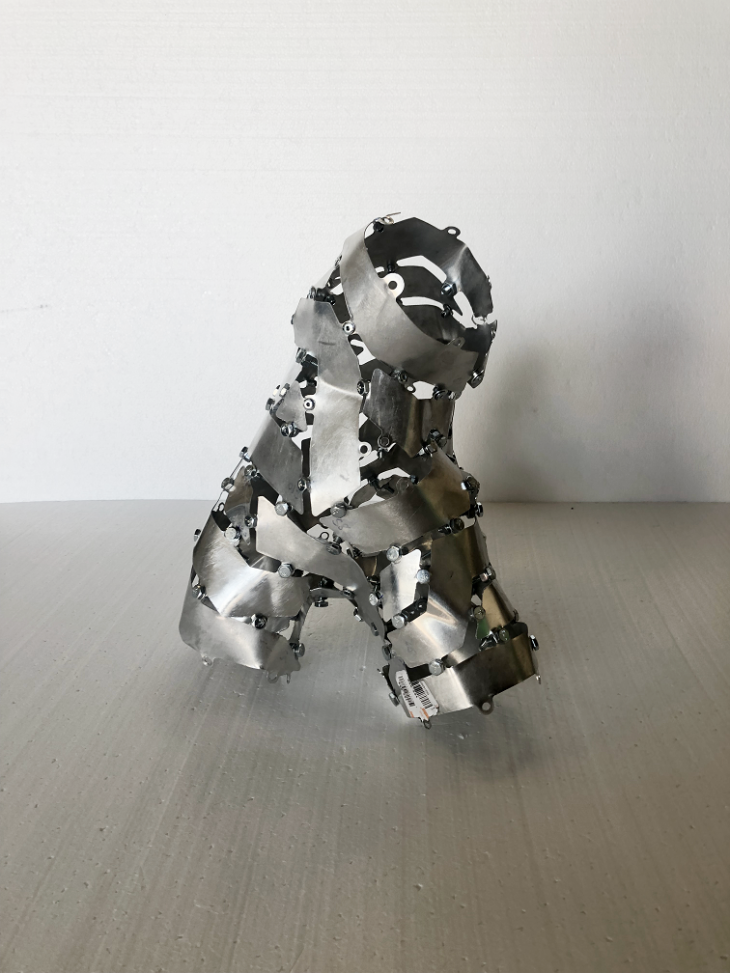
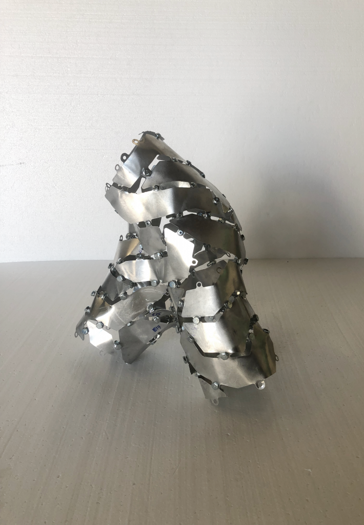
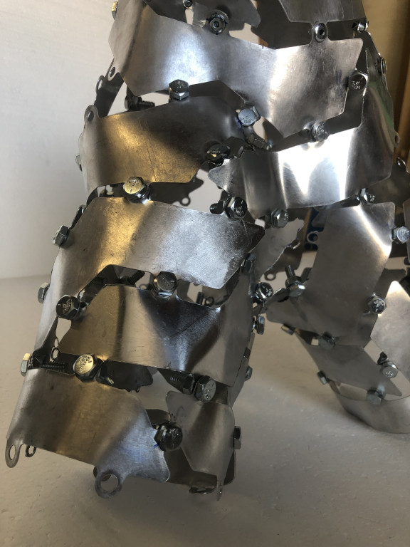
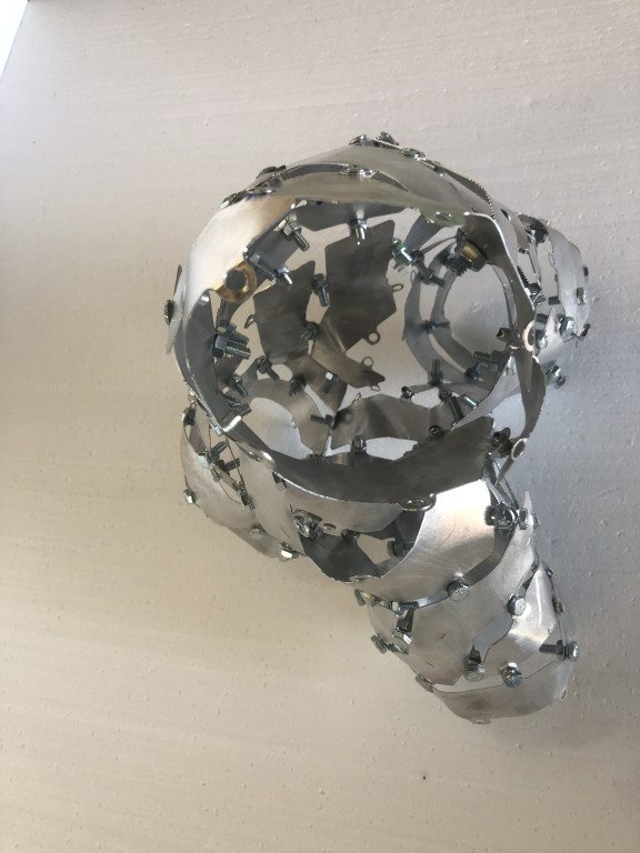
The initial full scale prototype model in aluminum was made using a mix of 16 gauge and 20 gauge thicknesses, due to the availability of material. A traditional 3-axis heavy duty CNC with a 6.0 mm dia. O’flute bit was used for the cutting. Once the assembly began, it became evidently clear that the material was thick and hard to manipulate. However, we managed to assemble the lower half of the model successfully. Another thing to note was that the initial trial with rivets did not work successfully. Due to the limitation of the 6 mm CNC bit, the minimum hole size on the tabs was also the same at 6 mm. However, the largest size of the rivets that could be procured was 4.76 mm. Although after being pressed, the rivets balloon to approx. 6 mm, it was still tight enough where the rivets were slipping through the holes with enough pressure from the assembly process. At this point we moved on to using a 6 mm nut and bolt assembly which worked perfectly.
After facing the difficulties with the first iterations, we moved on to trying a second digital model that was modeled using the multi-pipe component in Grasshopper. This would be a good comparison with the first iteration but still complex enough to justify the usage of the shortest walk stripping technique. For comparison purposes, we used the same script as the first iteration. The following video shows the process for this second digital model.
Iteration 02 – Shop Drawing 01
Iteration 02 – Shop Drawing 02
For the physical fabrication, this time we utilized 24 gauge Aluminum which was much more workable. Similar to the previous iteration, we utilized the 6 mm diameter nuts and bolts assembly.
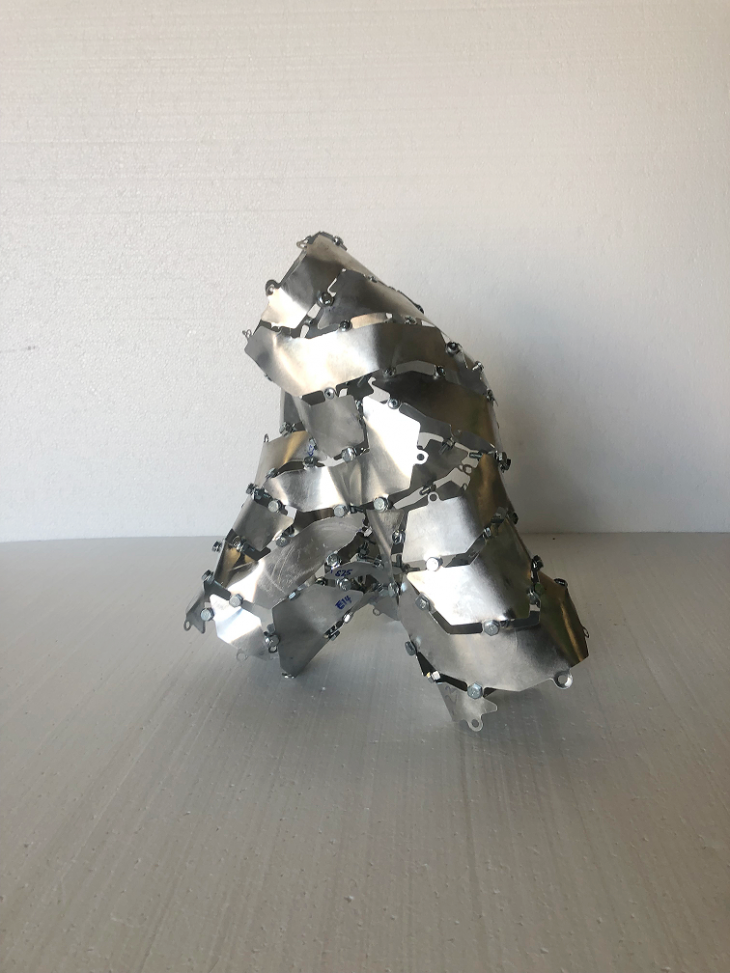

Each iteration taught us new lessons that we could apply to the next one. In conclusion, we found that specific complex models have specific rationalization, material, fastening and fabrication needs. Through the lessons learned in this project, we hope to continue developing process pipelines that take us from conceptual design to fabrication and installation.
Geometrical Optimization is a project of IAAC, Institute for Advanced Architecture of Catalonia developed in the Master in Advanced Computation for Architecture & Design in 2020/21 by:
Students: Aleksandra Jastrzębska and Sumer Matharu
Faculty: David Andrés León and Dai Kandil