Brief
This project defines a new methodology to sort and locate the material of a pre-demolition site to create a more reliable digital library (platform) of the resources available in old buildings. The purpose is to reduce the demolition waste generated by using the obsolete constructions as a mine for future buildings. In order to do that, an a sample location scanned with Parrot Bebop2 and with the images taken, materials sorted with a classification algorithm.
HOW DOES IT WORK?
WHAT VALUE DO WE PROVIDE?
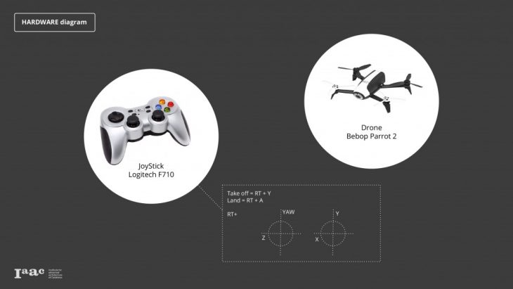
HARDWARE
Eventough the battery life time would be longer and image stability would be higher with a turtlebot, we used a Parrot Bebop2 drone since we would have problems with exterior inspection, reaching high parts and rough terrains in demolition site with turtlebot.
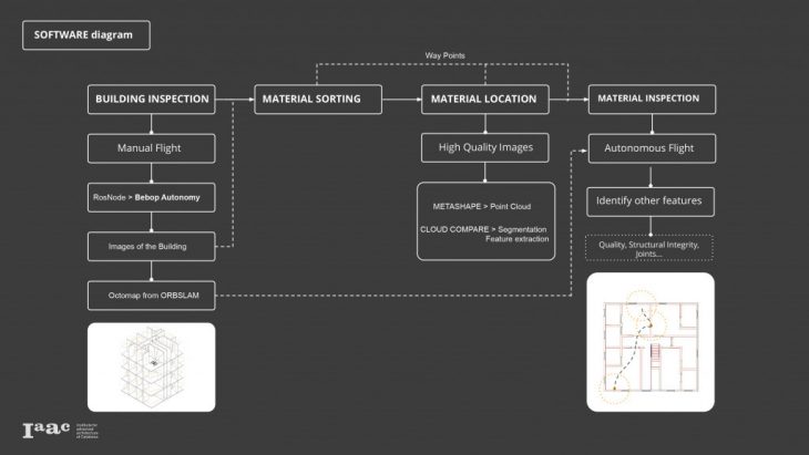
BUILDING INSPECTION
In order to digitalise the process of creating a material dataset the first step is to perform a manual flight to capture images from the demolition site. The drone we are using is a parrot bebop2 so we are using the corresponding library to control the drone via ROS.
Steps:
1- Place DRONE inside the cage
2- Connect to Bebop2Power Wi-Fi Network
3- Commands:
Terminal 1. To start Drone via ROS
$ locate libarcommands.so
answer: /opt/ros/melodic/lib/parrot_arsdk/libarcommands.so
$ export LD_LIBRARY_PATH=$LD_LIBRARY_PATH:/opt/ros/melodic/lib/parrot_arsdk/
$ roslaunch bebop_driver bebop_node.launch
(It will give errors if its not connected to the drone)
Terminal 2. To use the Joystick Controller
* cd iaac_eurecat_ws/src/bebop_autonomy/ bebop_tools/config
$ roslaunch bebop_tools joy_teleop.launch
Terminal 3. Drone camera
$ rosrun image_view image_view image:=/bebop/image_raw
Terminal 4. To save images
$ cd Documents/ (name of the folder where we want to save the documents)
$ rosrun image_view image_saver image:=/bebop/image_raw.
* Control + C > cancel (when the operation is finished)
</p>
SORTING
For all of our captured imagery from the initial inspection, we want to annotate localizations of our relevant materials, both for 3d reconstruction and display to the user. To do this, we apply a material classification algorithm to a grid of smaller patches of the image, and colorize accordingly.
Our classifier system is trained with one set of images for each category, both close up to describe the texture of the material, and as part of various building elements to describe its shape. Finally we have included a None category which contains imagery of other people and objects that will commonly be found in a demolition site, in order to avoid false positives.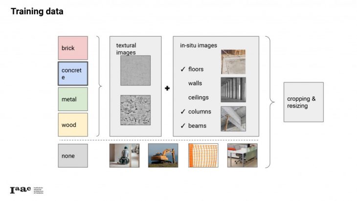
The actual classification starts with a mathematical description of the regions around certain points of interest, or features. In this case, the algorithm (GFTT) finds these features at the ‘corners’ between edges in image brightness. The descriptor algorithm (BRISK) then performs a series of simple binary comparisons of brightness in a pattern around the feature, and combines these together in a binary string. THese descriptions can be clustered together to obtain a limited set of ‘code-words’ that can describe our images, and a model is trained associating specific histogram-concentrations of these codewords with each of our categories.
These descriptions are clustered together to find a set of ‘visual words’ that can describe the images of our chosen subject matter. Images can be assigned to a category by analyzing how many of the visual words that correspond to the category also appear in the image.
Finally, these predictions are weighted with a simple comparison of the histograms of hue and saturation from the image, compared to the average histograms of each category.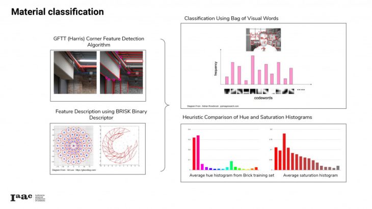
We use this classification method to localize areas of a specific material in our drone flight images. At its most basic, we divide the image into a grid of patches and apply the classification separately. We’ve found our classifier works best on image patches at least 100 pixels on a side. To obtain higher-resolution results, we move this hundred-pixel window in smaller increments for a series of overlapping classifications, and then average out the predictions for each smaller subpatch. These predictions are also weighted with some simple heuristics looking at the average trends of hue and saturation in each category.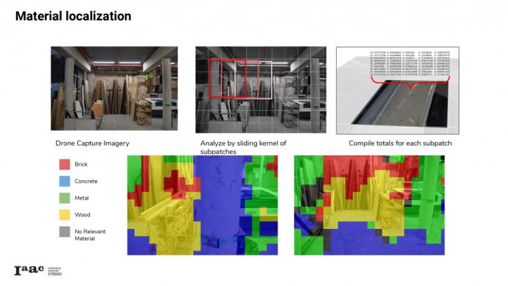
For further details: Github repository
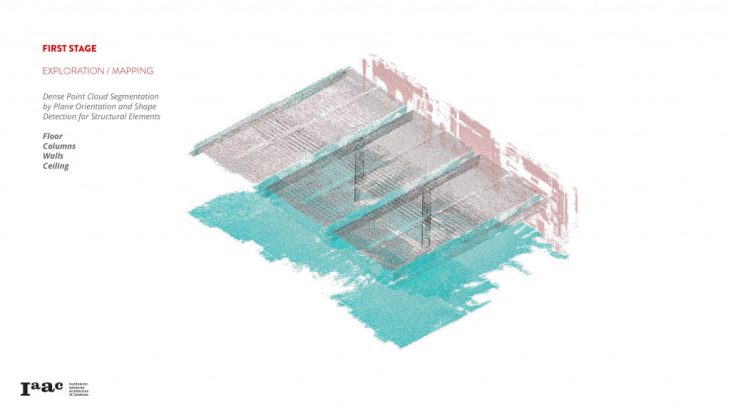
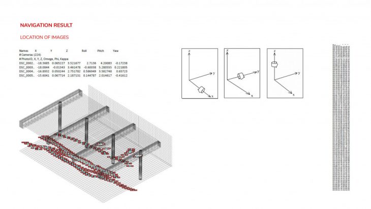
LOCATION
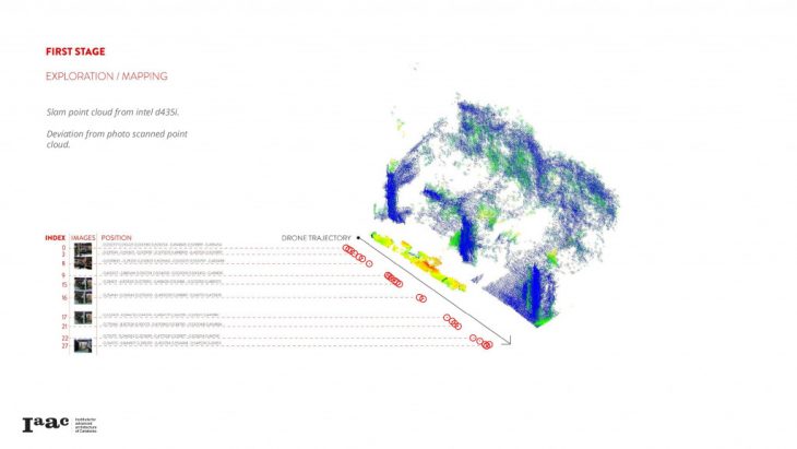
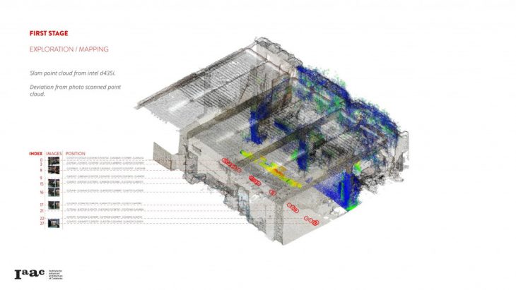
From the exploration flight we have two desired outputs, the first one being an octomap from OrbSlam2 for a further autonomous flight and the second one a colored dense point cloud from photogrammetry. The point cloud will be used to produce a 3D environment where all data acquired will be shown. e shown.
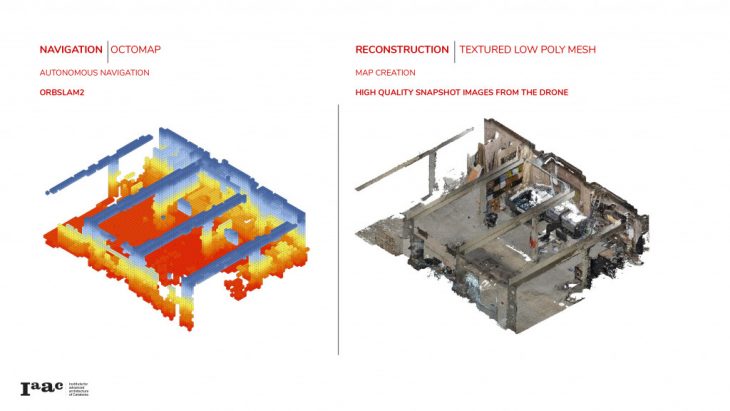
Outputs (Navigation / Reconstruction):
</p>
TESTING
Navigation Process
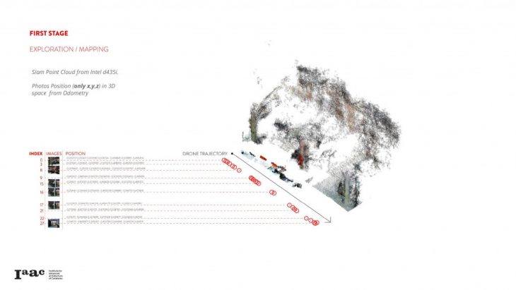
The next images show our experiments with OrbSlam2 using the drone camera and Slam with the depth camera D435i in order to get an octomap for a further material detailing using autonomous flight.
Repositories used:
Repository 1
Repository 2
Manual Exploration: ORBSLAM2
</p>
</p>
</p>
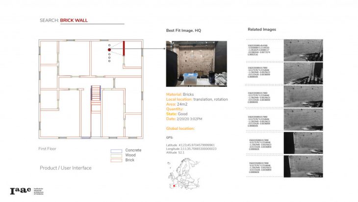
MATERIAL / ELEMENT LOCATION
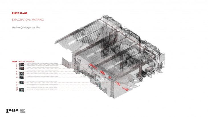
The next images show our experiments using the high quality images from the drone to reconstruct the 3D environment. Two different sets of point clouds were necessary to create the complete point cloud. The environment was then processed in Cloud Compare to extract the architectural and structural elements from the point cloud. After having all the elements as geometry files, the surfaces or meshes were imported into Grasshopper for further cleaning. The output of the whole process were clean quad mesh elements named as: ceiling, beams, columns, floor and wall.
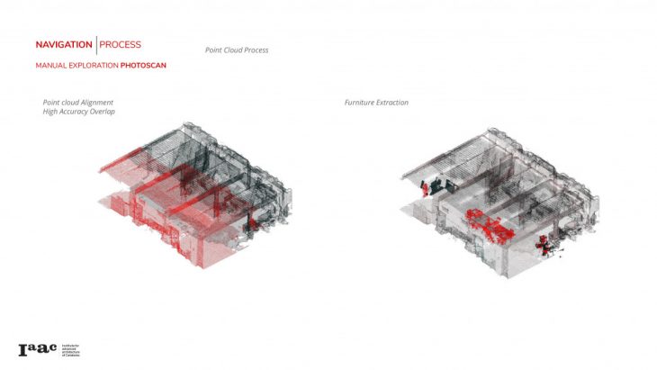
The next step was to implement the image retrieval from the 3D environment. Each time you select an element such as “floor” you get all the images related in position and rotation to that geometry.
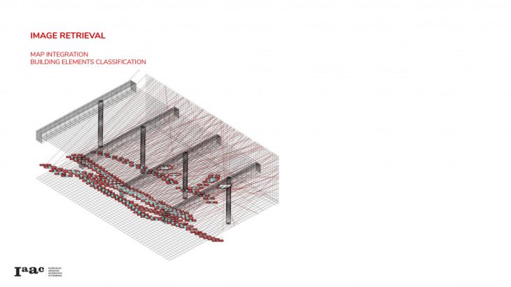
Map Integration / Building Elements Classification:
</p>
Map Integration / Building Elements + Materials:
</p>
Since there are areas that doesn’t have accurate data from the first flight, a second flight for material inspection is needed.
MATERIAL INSPECTION
In order to perform the second flights, way points should be used.
Steps:
1-Place DRONE
2-Connect to Bebop2Power Wi-Fi Network
3- Commands:
Terminal 1. To start Drone via ROS
$ iaac_eurecat_ws/
$ locate libarcommands.so
answer: /opt/ros/melodic/lib/parrot_arsdk/libarcommands.so
$ export LD_LIBRARY_PATH=$LD_LIBRARY_PATH:/opt/ros/melodic/lib/parrot_arsdk/
* go inside cd + iaac_eurecat_ws/src/bebop_autonomy/ bebop_driver/launch
$ roslaunch bebop_driver bebop_node.launch
(It will give errors if its not connected to the drone)
Terminal 2. To start Drone via ROS
go inside iaac_eurecat_ws /src/bebop_autonomy/scripts
$ python bebop_position_controller_yaw_pid.py
Use the keyboard for movement
* to imput the points modify the way points yaw-py
Keyboard:
S= Stop and go to zero
L= Land
N= Navigation mode
T= Take off
* make sure to reset the terminals before starting again. And have the finger in L in case the drone doesn’t behave as spectated.
</p>
Digitalizing Material Collation from Pre-Demolition Sites is a project of IaaC, Institute for Advanced Architecture of Catalonia developed in the Masters of Robotics and Advanced Construction in 2019/20 by: Students: Anna Batallé, Irem Yagmur Cebeci, Matthew Gordon, Roberto Vargas Faculty: Angel Munoz, Soroush Garivani