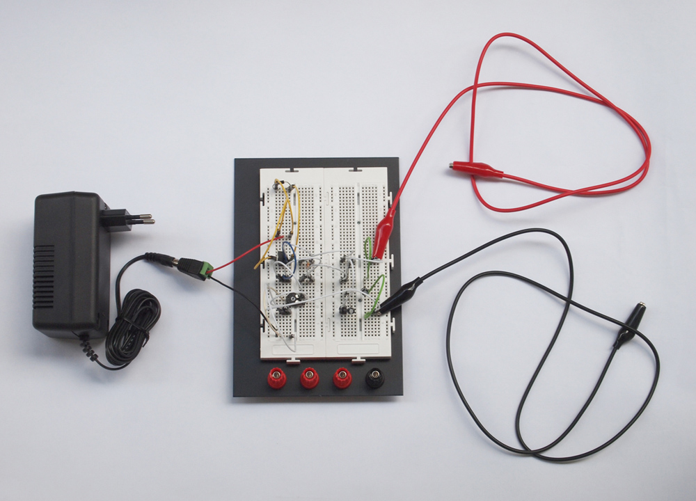
 An electronic test circuit for electroactive polymer actuator. The aim of this circuit is to test the possibility of controlling the polymer actuator with a microcontroller (Arduino). The circuit consits of 3 blocks 1) Variable power supply – provides stable voltage 0-12V and current of 125 mA for the high voltage converter. 2) High voltage converter and polymer actuator – converter converts incoming voltage of 0-12V and transforms it to high voltage (0-6kV). High voltage is essential for actuation of polymer. Graphite cathode and anode start to actuate the polymer matter around 2 kV. Positive and negative output of the converter are directly connected to the anode and cathode of the actuator. Bleeder resistors discharge the electric charge after the circuit is off. 3) Arduino microcontroller and digital potentiometer MCP4131 – control the behaviour of the actuator. Digital potentiometer has a range of 128 values. It is possible to add sensors to this circuit.
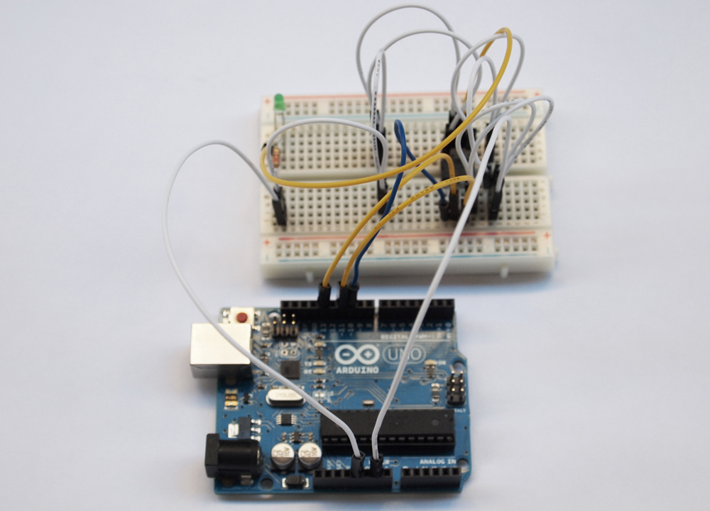
 digital potentiometer MCP4131 test circuit variable power supply test circuit
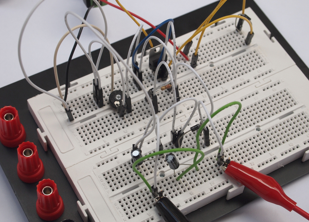
 variable power supply test circuit