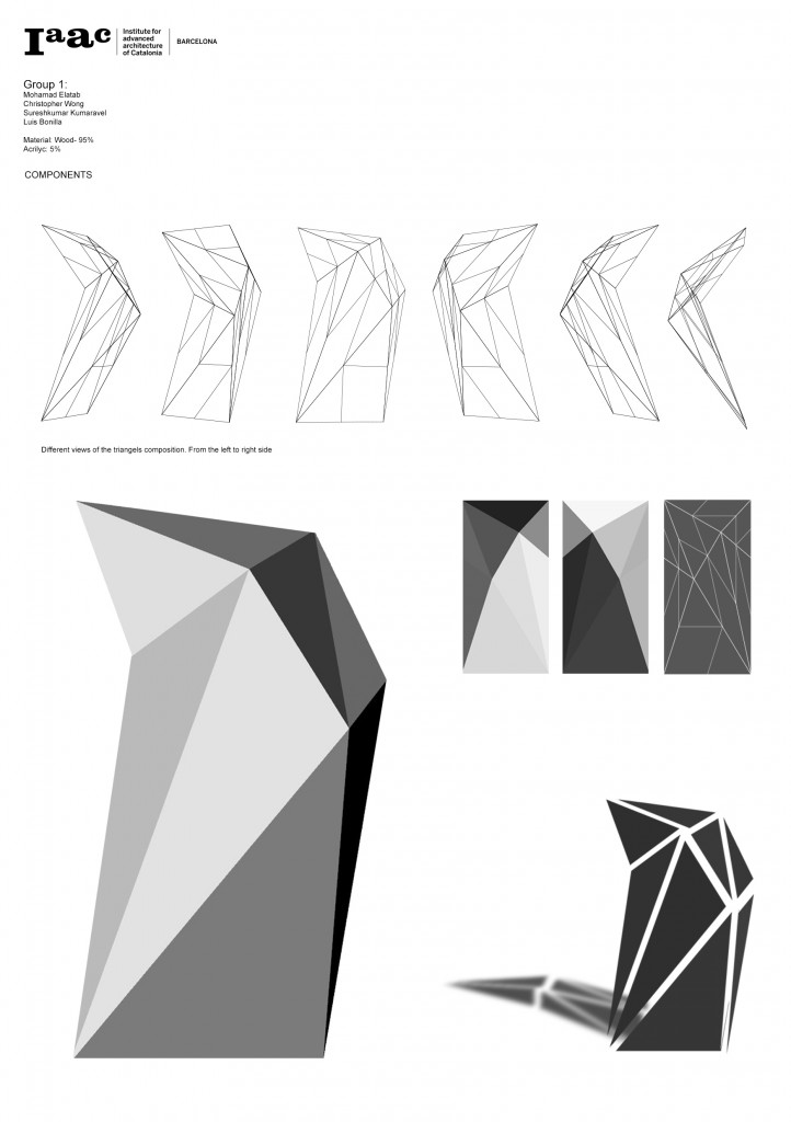
CONCEPT
How can a joint system for tessellated wood panels use acrylic to simultaneously integrally admit light and control the interface of the panels? In this system, each edge at which a panel meets another is physically penetrated by one or more acrylic joints which emerge from within the façade. Sets of collinear joints are then secured on the outside of the façade by a wood strip which passes through slots cut into the joints. By partially occluding the translucent joints with opaque material, narrow strips of light are created which emphasize the lines created by the panel joints.
METHODS
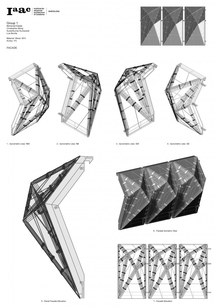
A significant geometrical challenge in the modelling of the façade was orienting the joints so that they are perpendicular to both panels that they connect. This was necessary because while laser cutting allows for the precise control of component geometry, it can only cut at 90 degrees relative to the surface of the material – so intersecting parts should join at a right angle for a close fit. The eventual solution involved the following algorithm:
- In Rhino, set the construction plane to one of the two surfaces.
- Use the bounding box command to draw a rectangle around the surface.
- If the length of the bounding box is not equal to the length of the join edge, scale it in the direction of the join edge so that it is.
- Repeat 1 through 3 for the other surface.
- Draw a triangle connecting the midpoint of the join edge and the midpoints of the two bounding box edges parallel to it.
Three-dimensional joints were then built using these triangles as guides for direction.
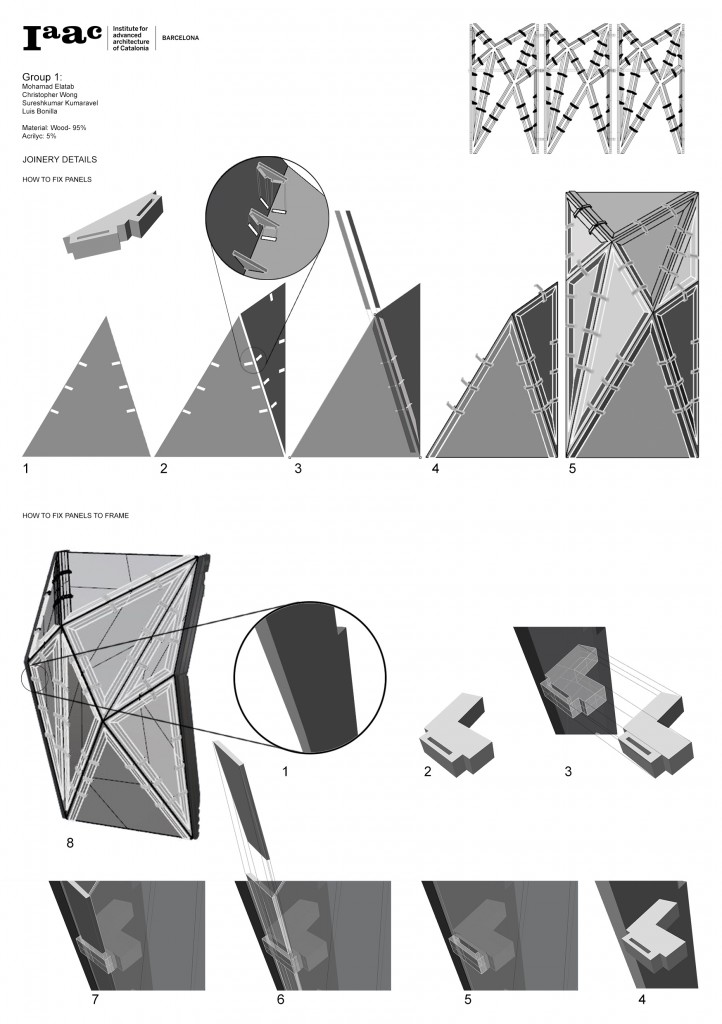
Physically, the joints are composed of five stacked identical pieces of acrylic. This allows for thickness and redundancy, which give resilience to the joint itself, while remaining easily fabricable by laser cutting. The brackets which connect the façade to the frame use the same logic, but in wood to accept a screwed connection.
GROUP 1
Students:
Bonilla Millan, Luis Andres
El Atab, Mohamad
Kumaravel, Sureshkumar
Wong, Christopher
DATA
Material: Plywood
Technique: Tessellation
Percentage: 95%
Translucent material: Acrylic
Percentage: 5%